Pinouts
Pinouts of boards, chips, modules and connectors: Arduino, ESP32, Raspberry Pi, sensors, displays, USB, HDMI and more, with their notes and specifications.
Arduino
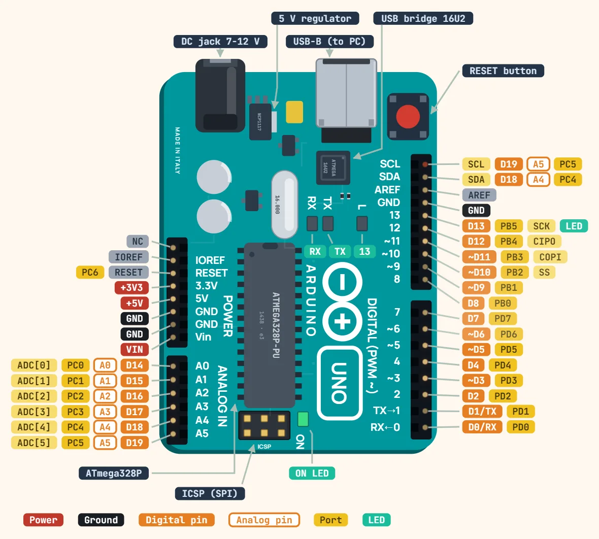 Arduino Uno R3Microcontroller: ATmega328P; Operating voltage: 5 V; Input voltage (recommended): 7–12 V
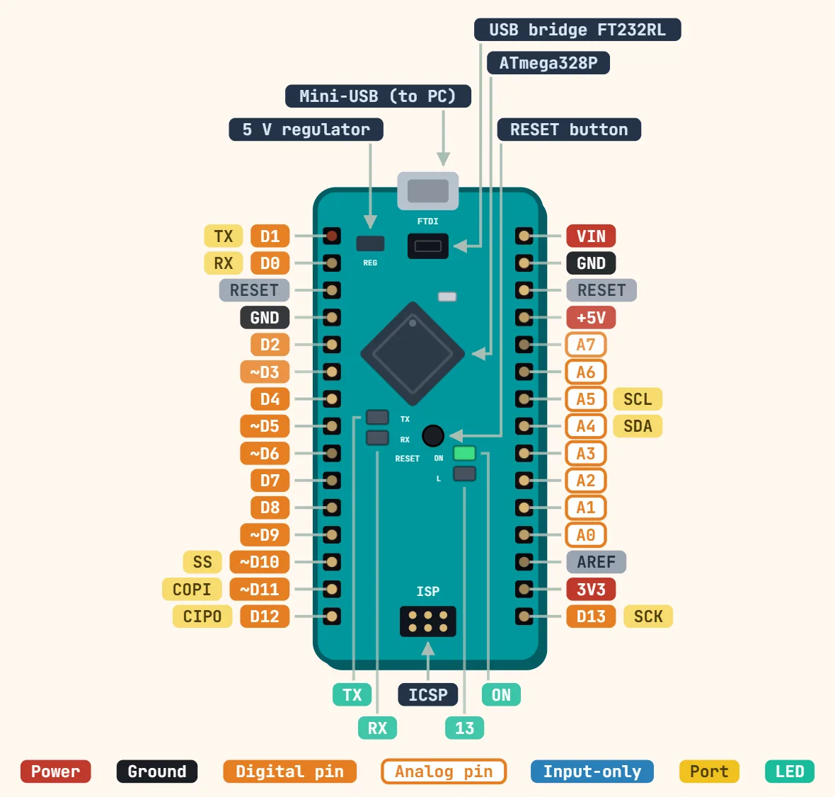 Arduino Nano (ATmega328P)Microcontroller: ATmega328P; Operating voltage: 5 V; Input voltage (VIN): 7–12 V
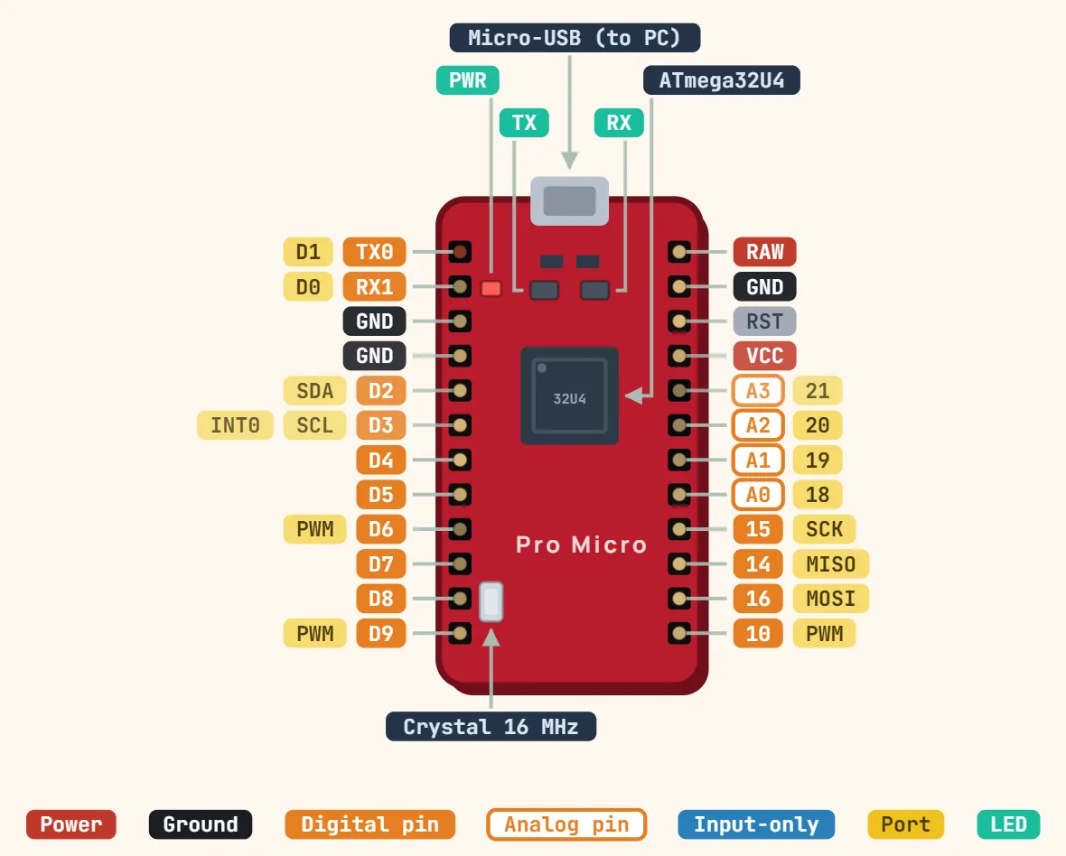 SparkFun Pro Micro (ATmega32U4)Microcontroller: ATmega32U4; Versions: 5 V / 16 MHz or 3.3 V / 8 MHz; Input voltage (RAW): up to 12 V (5 V version needs ≥ 6 V on RAW)
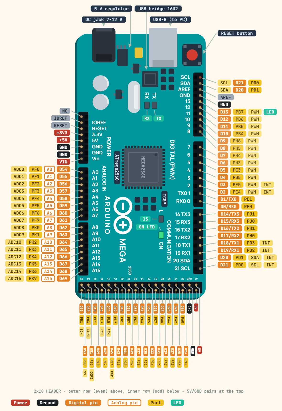 Arduino Mega 2560 Rev3Microcontroller: ATmega2560; Operating voltage: 5 V; Input voltage (recommended): 7–12 V
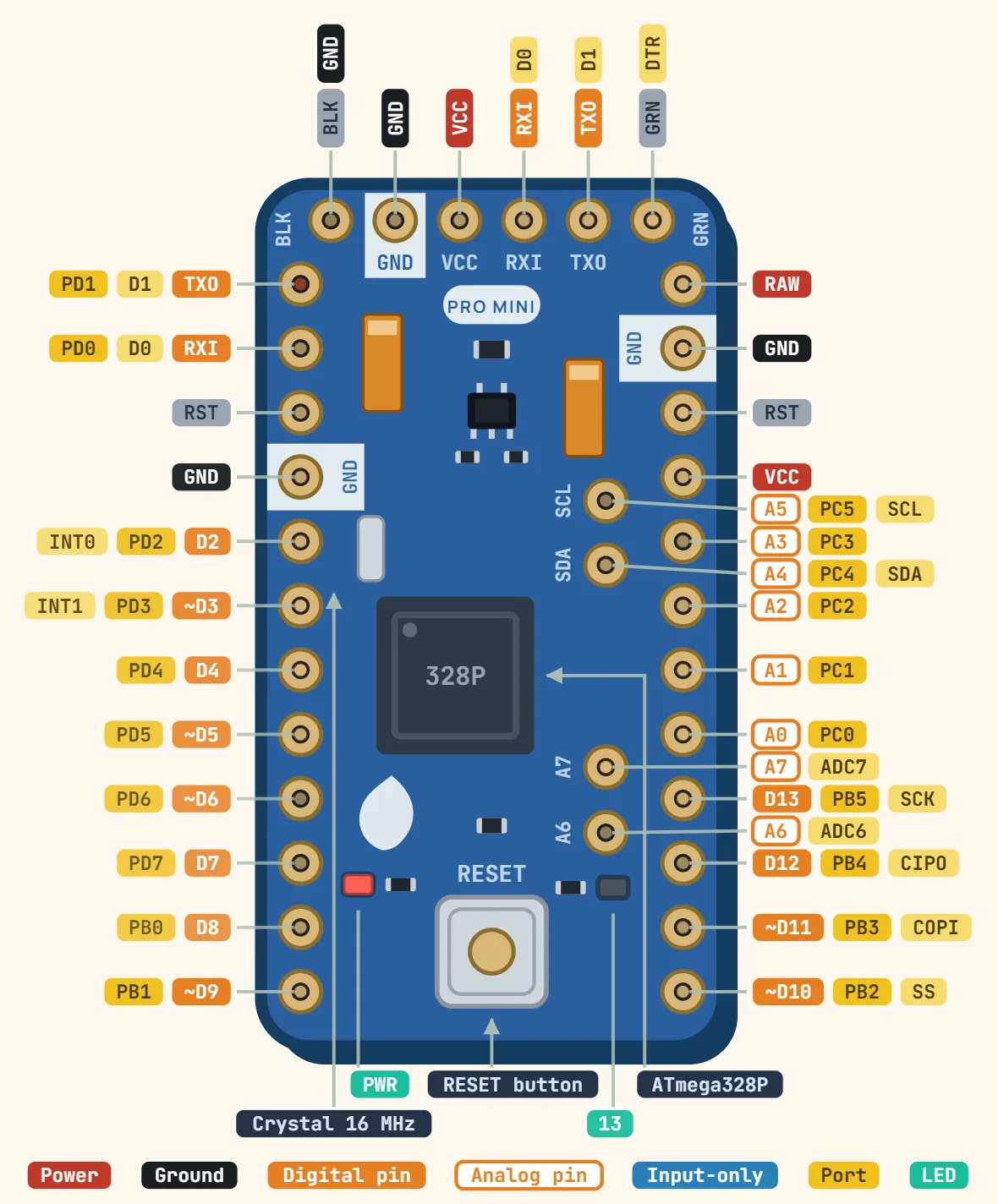 Arduino Pro Mini (ATmega328P)Microcontroller: ATmega328P; Versions: 3.3 V / 8 MHz or 5 V / 16 MHz; Input voltage (RAW): 3.35–12 V (3.3 V version), 5–12 V (5 V version)
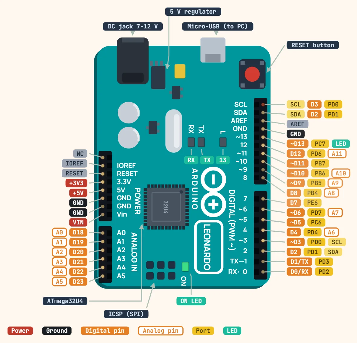 Arduino LeonardoMicrocontroller: ATmega32U4; Operating voltage: 5 V; Input voltage (recommended): 7–12 V
ESP
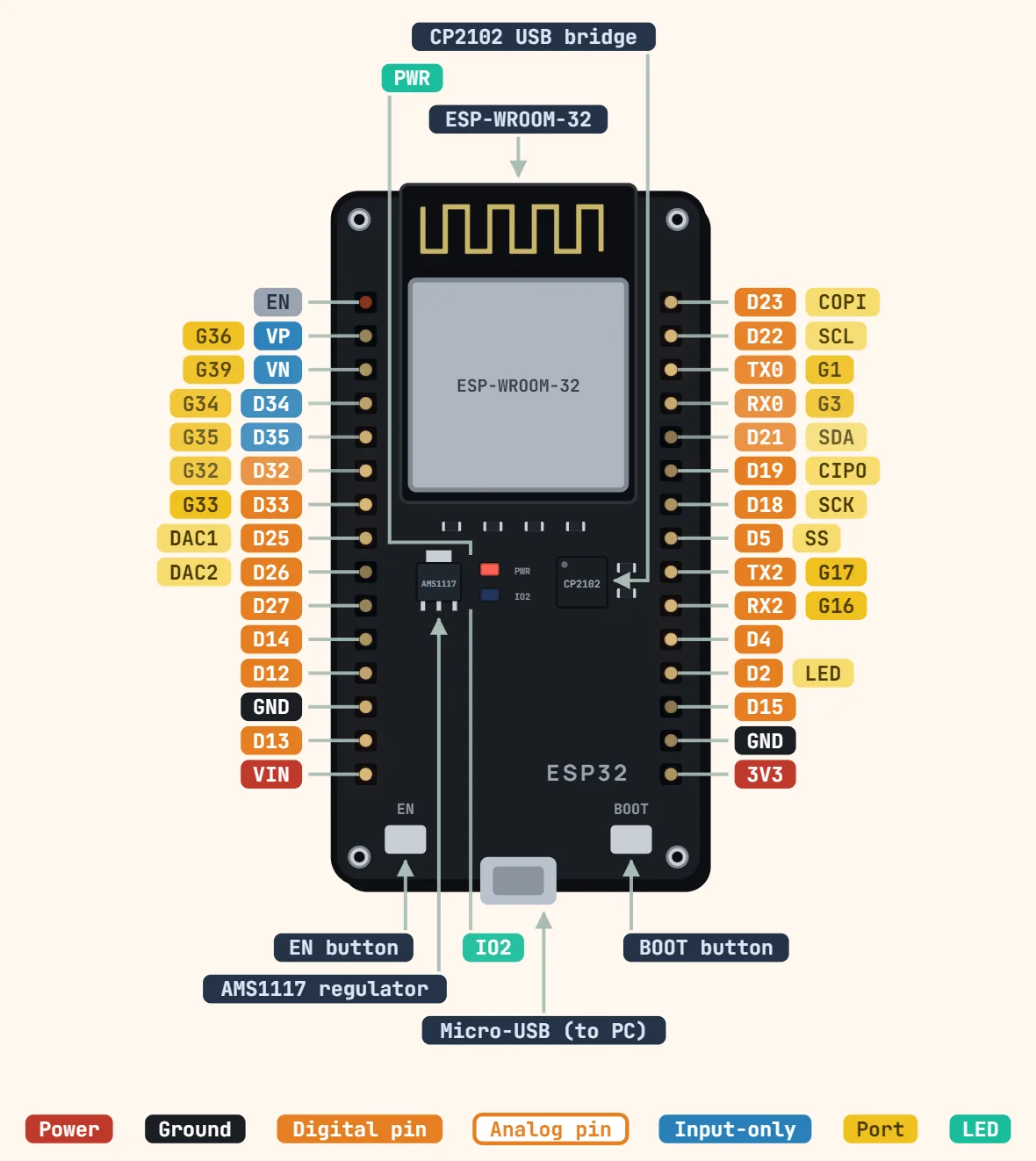 ESP32 DevKit V1 (30-pin)Module: ESP32-WROOM-32; CPU: Dual-core Xtensa LX6, up to 240 MHz; SRAM: 520 KB
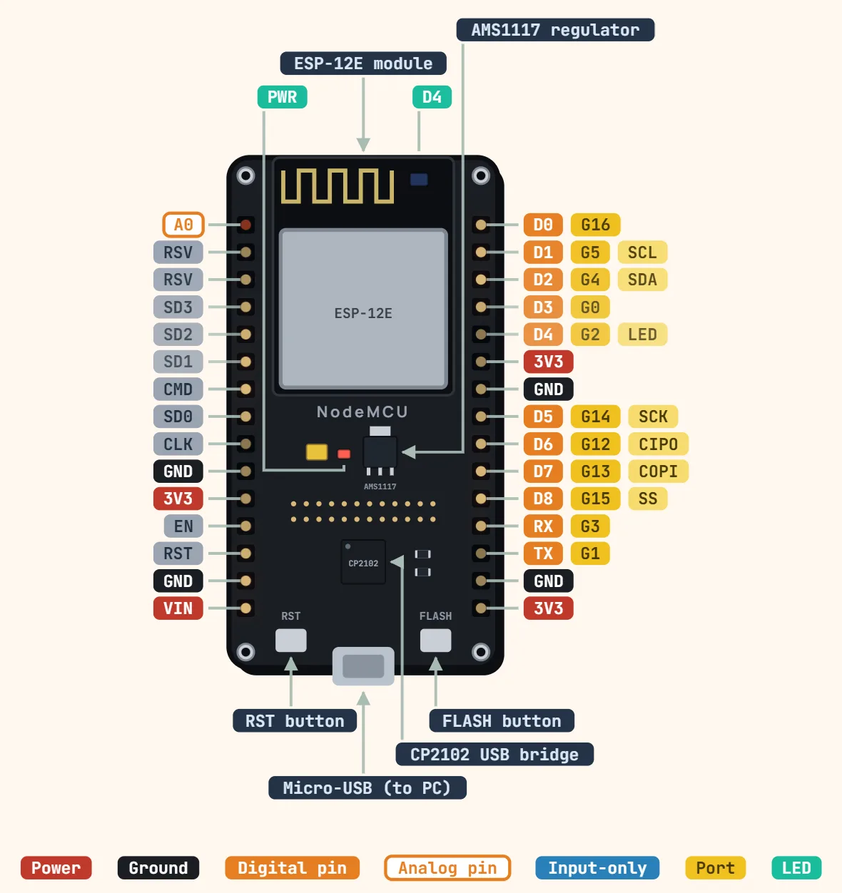 ESP8266 NodeMCUModule: ESP-12E/ESP-12F (ESP8266EX); CPU: Tensilica L106, 80 MHz (160 MHz option); Flash memory: 4 MB
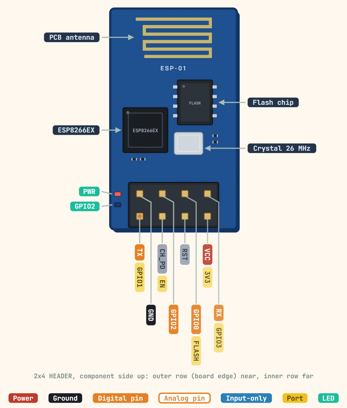 ESP-01 (ESP8266, 2×4 header)Chip: ESP8266EX; CPU: Tensilica L106, 80 MHz (160 MHz option); Flash memory: 512 KB (ESP-01) or 1 MB (ESP-01S)
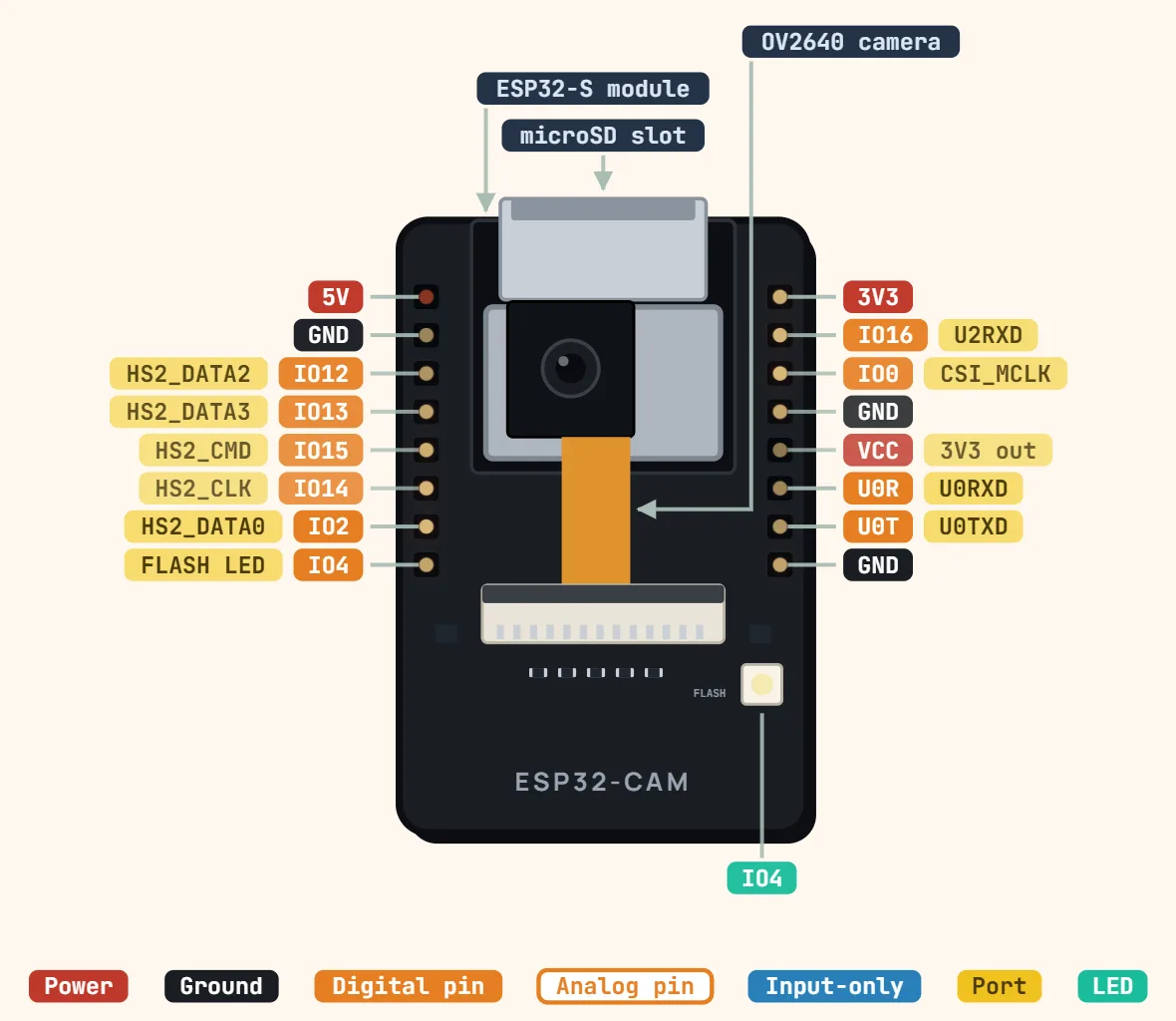 ESP32-CAM (AI-Thinker)Chip: ESP32 (dual-core, up to 240 MHz); PSRAM: 4 MB; Flash memory: 4 MB
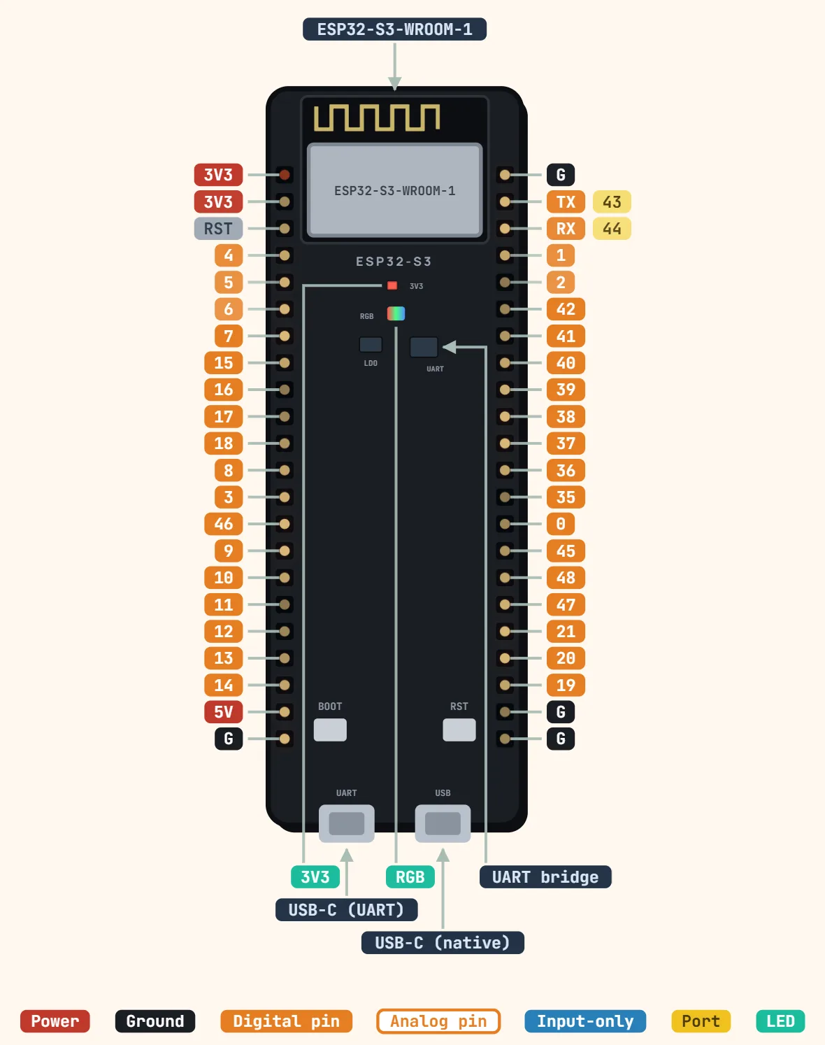 ESP32-S3 DevKitC-1Module: ESP32-S3-WROOM-1 (or -1U); CPU: Dual-core Xtensa LX7, up to 240 MHz; SRAM: 512 KB
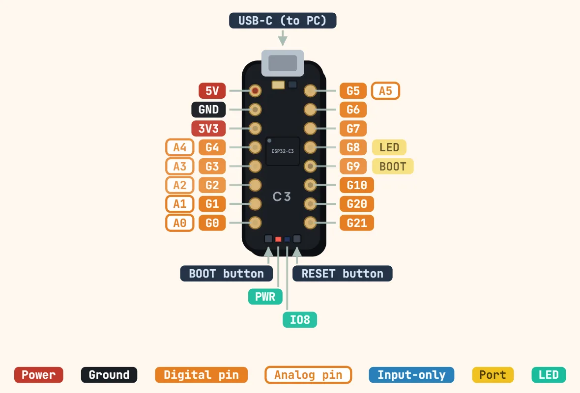 ESP32-C3 SuperMiniChip: ESP32-C3, single-core 32-bit RISC-V; Clock speed: 160 MHz; SRAM: 400 KB
Raspberry Pi
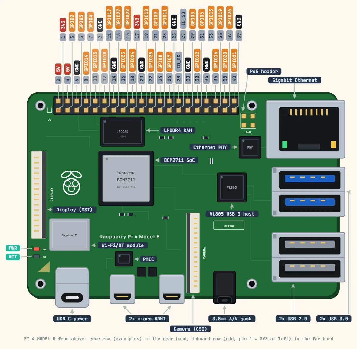 Raspberry Pi 4 Model B (40-pin GPIO)SoC: Broadcom BCM2711, quad-core Cortex-A72 (64-bit); Clock speed: 1.5 GHz (1.8 GHz on later board revisions); RAM: 1, 2, 4 or 8 GB LPDDR4
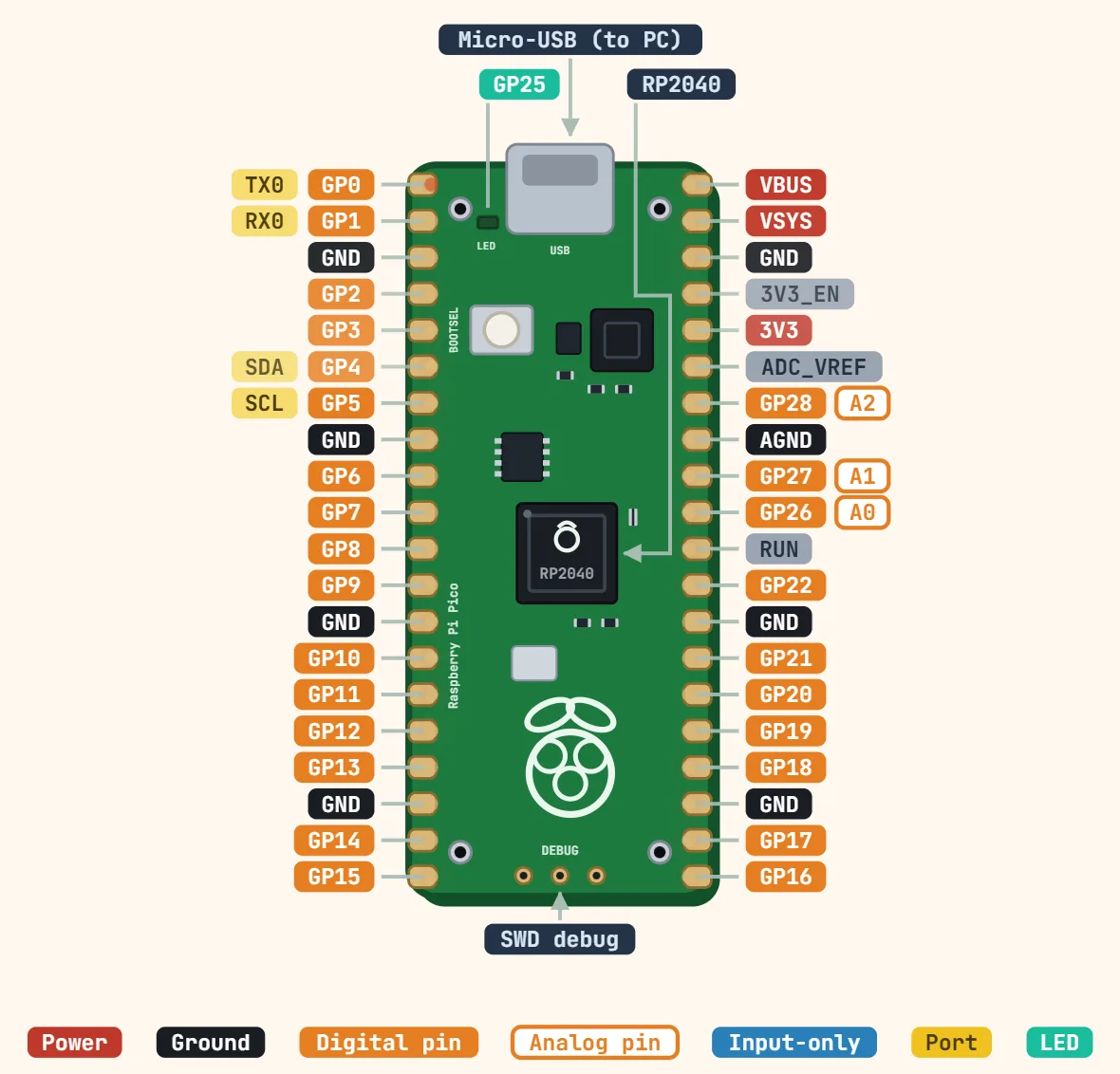 Raspberry Pi Pico (RP2040)Microcontroller: RP2040, dual-core Arm Cortex-M0+; Clock speed: 133 MHz; SRAM: 264 KB
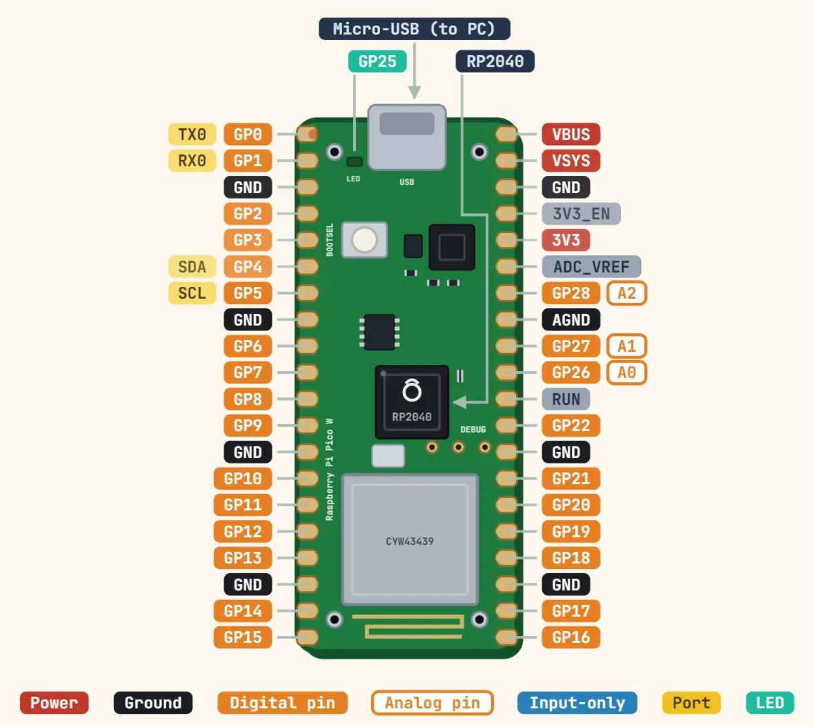 Raspberry Pi Pico W (RP2040 + CYW43439)Microcontroller: RP2040, dual-core Arm Cortex-M0+; Clock speed: 133 MHz; SRAM: 264 KB
STM32 & Teensy
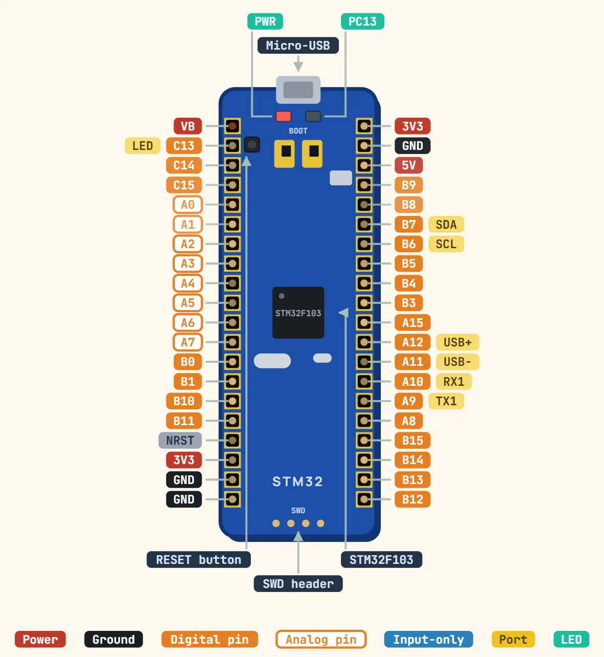 STM32 Blue Pill (F103C8T6)Microcontroller: STM32F103C8T6, Arm Cortex-M3; Clock speed: 72 MHz (8 MHz crystal); Flash memory: 64 KB (many chips actually have 128 KB)
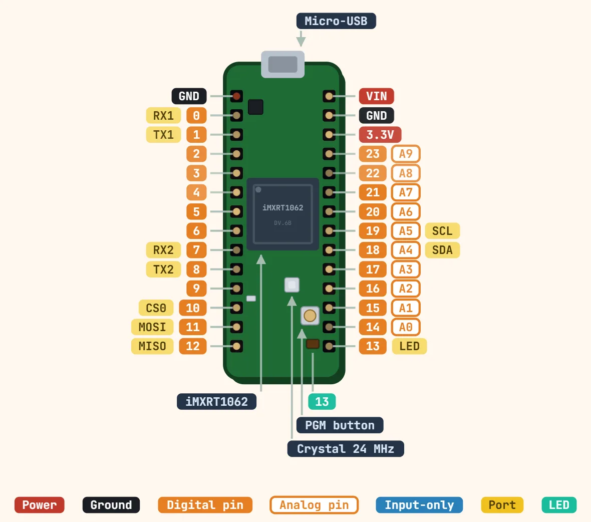 Teensy 4.0Processor: NXP i.MX RT1062, Arm Cortex-M7; Clock speed: 600 MHz; RAM: 1024 KB (512 KB tightly coupled)
- STM32 Black Pill (WeAct V3.0, F411CEU6)Microcontroller: STM32F411CEU6, Arm Cortex-M4F; Clock speed: 100 MHz (25 MHz crystal); Flash memory: 512 KB
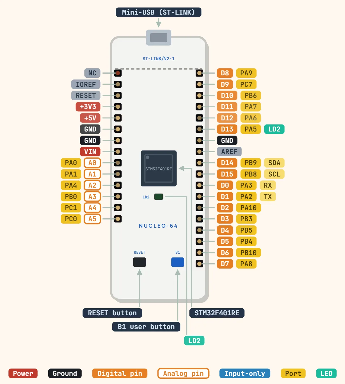 STM32 Nucleo-64 (e.g. NUCLEO-F401RE)Microcontroller: STM32F401RET6, Arm Cortex-M4F (F401RE); Clock speed: 84 MHz; Flash memory: 512 KB
Sensors
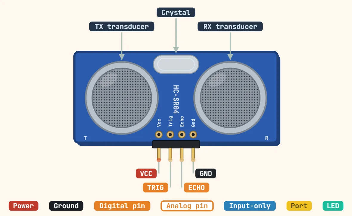 HC-SR04 ultrasonic distance sensor (4-pin)Supply voltage: 5 V DC; Working current: 15 mA; Logic level: 5 V (TRIG and ECHO)
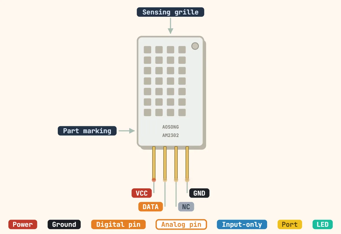 DHT11 / DHT22 temperature & humidity sensor (4-pin)Supply voltage: DHT11: 3–5.5 V; DHT22: 3.3–6 V; Interface: Single-wire digital (proprietary, not 1-Wire); Pull-up on DATA: 4.7–10 kΩ to VCC
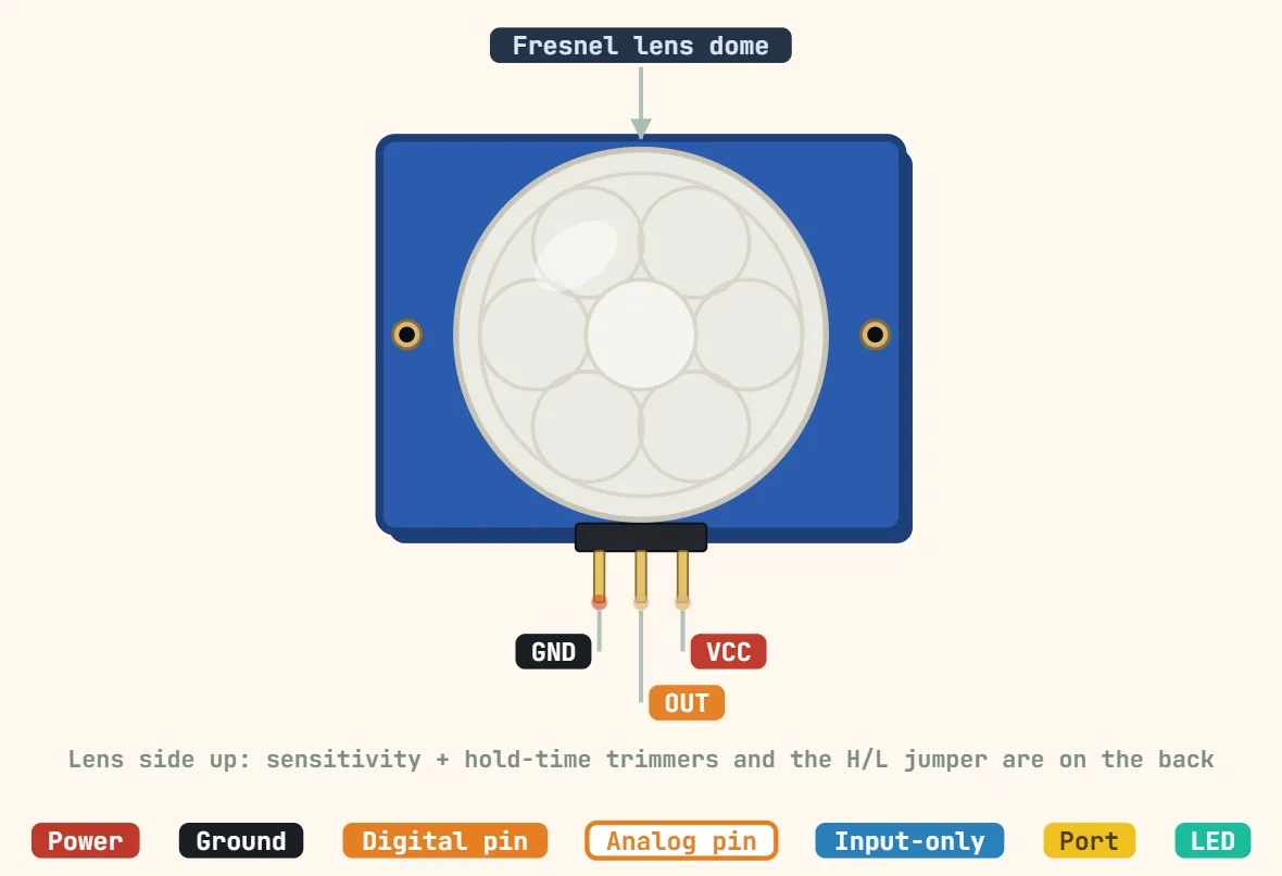 PIR motion sensor (HC-SR501, 3-pin)Supply voltage: 4.5–20 V DC (5 V typical, onboard 3.3 V regulator); Quiescent current: < 50 µA; Output level: 3.3 V HIGH / 0 V LOW
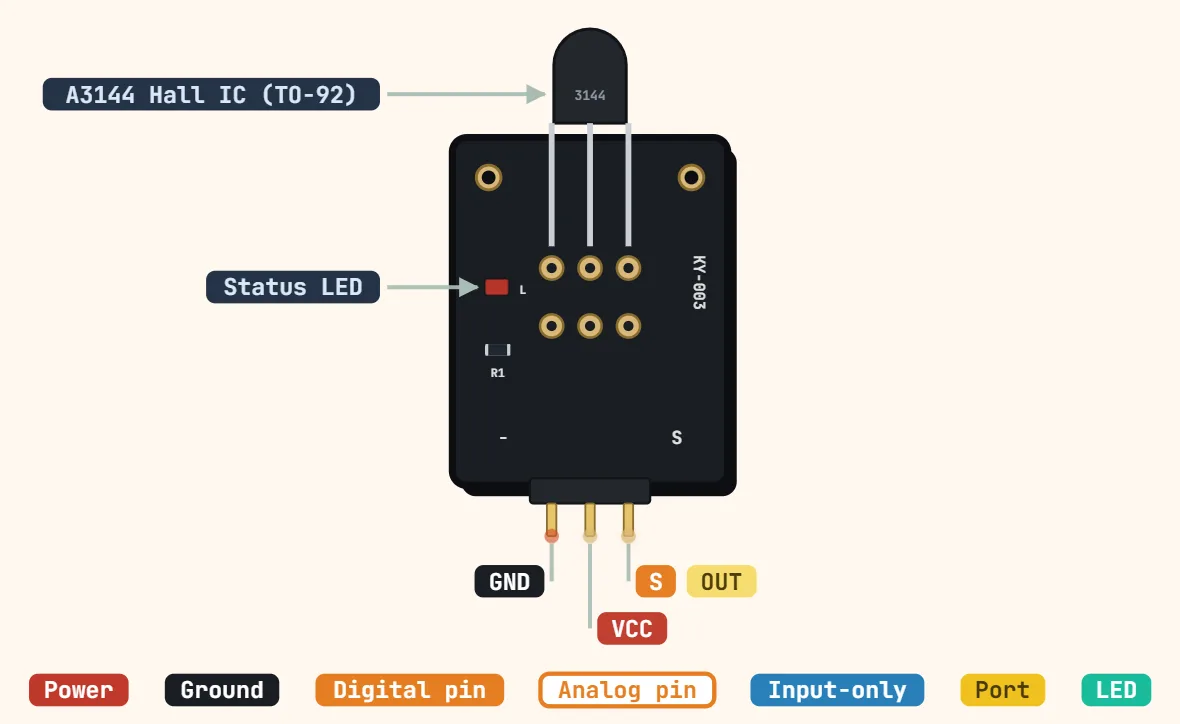 Hall effect sensor module (KY-003, A3144, 3-pin)Sensor IC: A3144 unipolar Hall-effect switch; Supply voltage: 4.5–24 V (A3144 rating; 5 V typical); Supply current: ≈4.4 mA typical (chip)
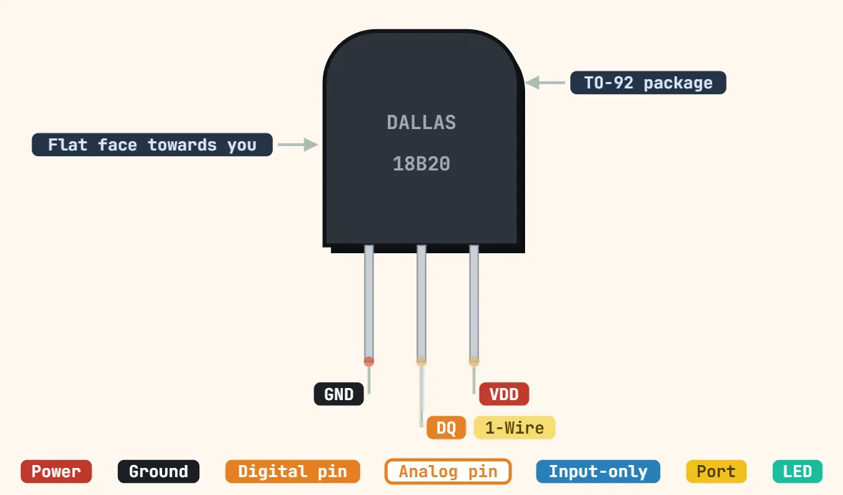 DS18B20 temperature sensor (1-Wire, TO-92)Supply voltage: 3.0–5.5 V (or parasite power from DQ); Interface: 1-Wire, unique 64-bit ROM code per sensor; Pull-up on DQ: 4.7 kΩ to VDD
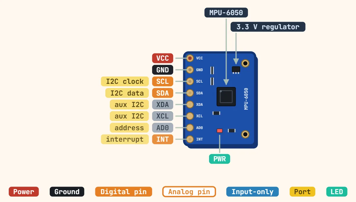 MPU6050 accelerometer/gyro module (GY-521, I2C)Board supply: 3.3–5 V (onboard 3.3 V regulator); Chip supply: 2.375–3.46 V; Interface: I2C, up to 400 kHz
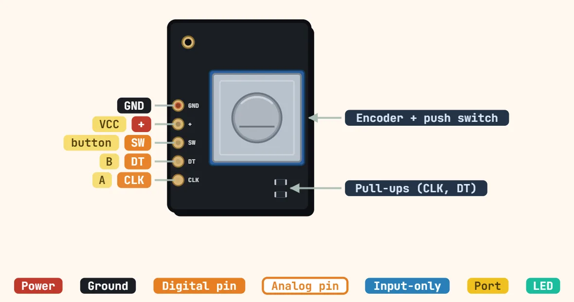 Rotary encoder module (KY-040, 5-pin)Supply voltage: 3.3–5 V; Output: 2-channel quadrature (CLK, DT); Pull-ups: 10 kΩ on CLK and DT; none on SW
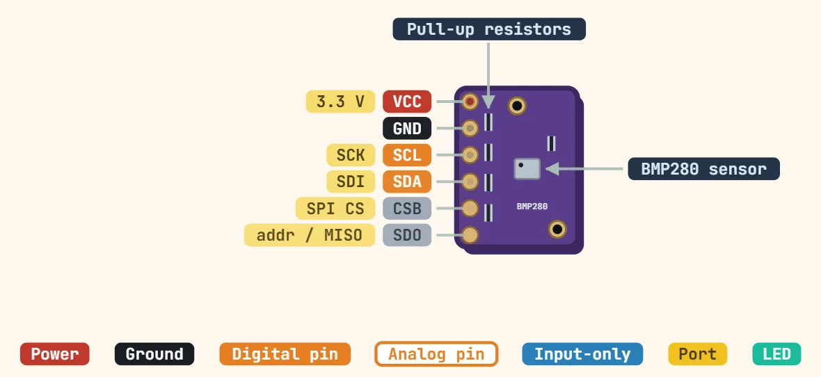 BMP280 / BME280 barometric module (GY-BMP280, I2C/SPI)Board supply: GY-BMP280-3.3: 3.3 V only; boards with LDO: 3.3–5 V; Chip supply: 1.71–3.6 V; Interface: I2C (up to 3.4 MHz) or SPI (up to 10 MHz)
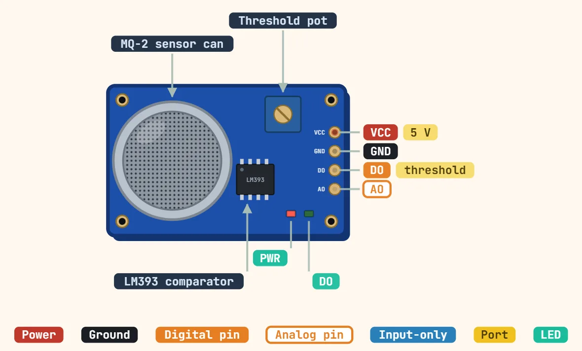 MQ-2 gas sensor module (4-pin)Supply voltage: 5 V; Heater resistance: 33 Ω ±5 %; Heater current: ≈150 mA
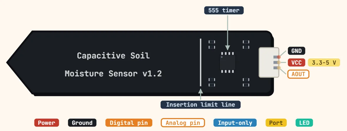 Capacitive soil moisture sensor module (v1.2)Supply voltage: 3.3–5.5 V; Output voltage: 0–3.0 V analog (higher = drier); Operating current: ≈5 mA
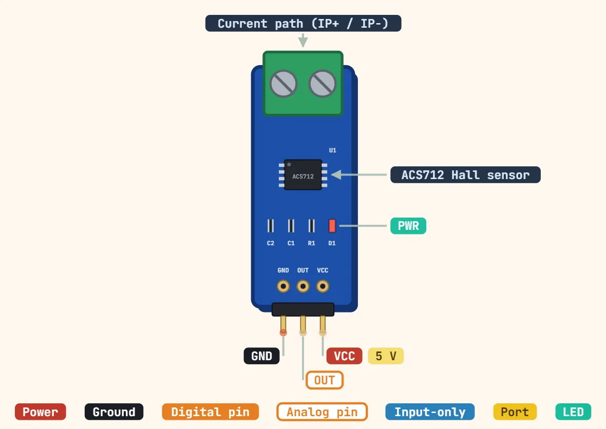 ACS712 current sensor moduleSupply voltage: 4.5–5.5 V (5 V typical); Measuring range: ±5 A / ±20 A / ±30 A (by variant); Sensitivity: 185 / 100 / 66 mV/A (5 A / 20 A / 30 A)
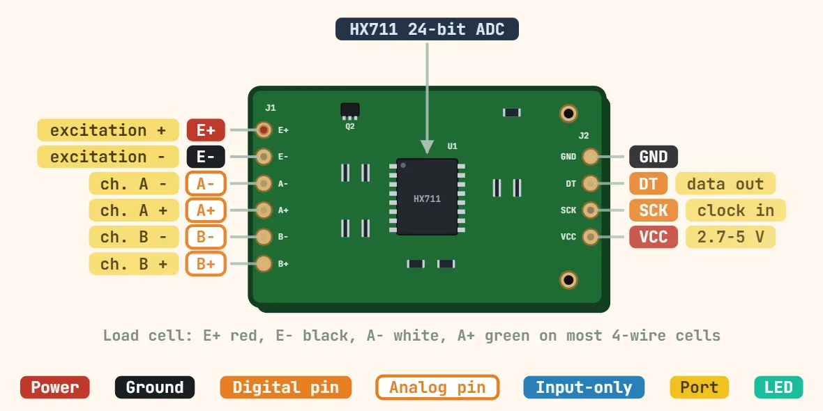 HX711 load-cell amplifierSupply voltage: 2.6–5.5 V; ADC resolution: 24 bit; Channel A gain: 128 or 64 (±20 mV / ±40 mV full scale at 5 V)
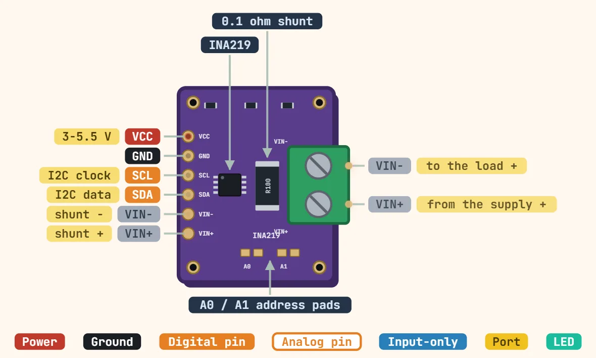 INA219 current/power monitor (GY-219)Supply voltage: 3–5.5 V; Interface: I2C; I2C address: 0x40 default (0x41, 0x44, 0x45 via A0/A1)
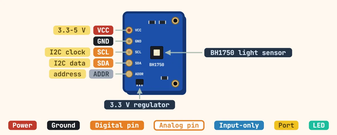 BH1750 light sensor (GY-302)Board supply: 3.3–5 V (onboard regulator); Chip supply: 2.4–3.6 V; Interface: I2C, up to 400 kHz
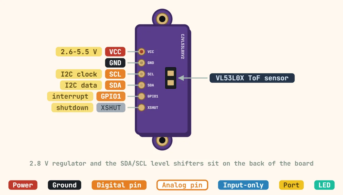 VL53L0X time-of-flight distance sensor (GY-VL53L0XV2 module, I2C)Board supply: 2.6–5.5 V (onboard 2.8 V regulator); Chip supply: 2.6–3.5 V; Interface: I2C, up to 400 kHz
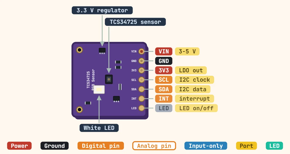 TCS34725 RGB color sensor module (I2C)Board supply (VIN): 3–5 V on boards with LDO (check clones); Chip supply: 2.7–3.6 V; Interface: I2C, up to 400 kHz
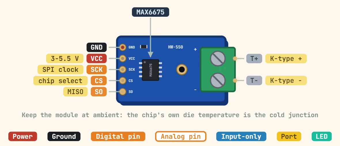 MAX6675 K-type thermocouple amplifier (SPI module)Supply voltage: 3.0–5.5 V; Thermocouple type: K; Measuring range: 0–1024 °C
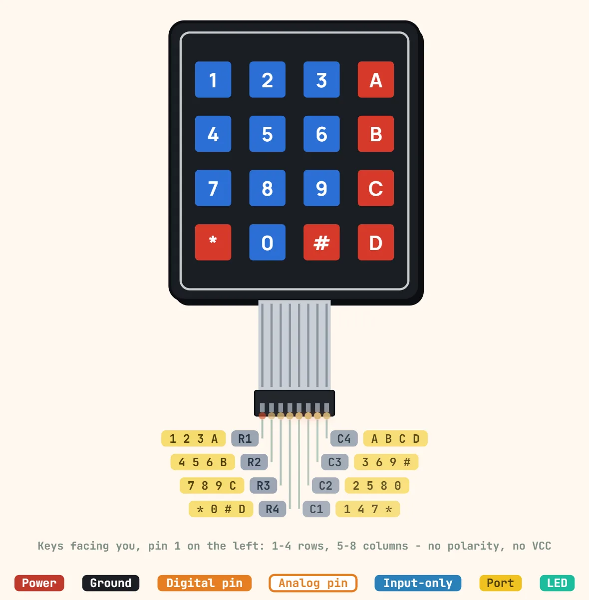 4×4 matrix membrane keypad (8-pin ribbon)Keys: 16 (4 rows × 4 columns); Type: Passive switch matrix, no diodes; Power: None needed
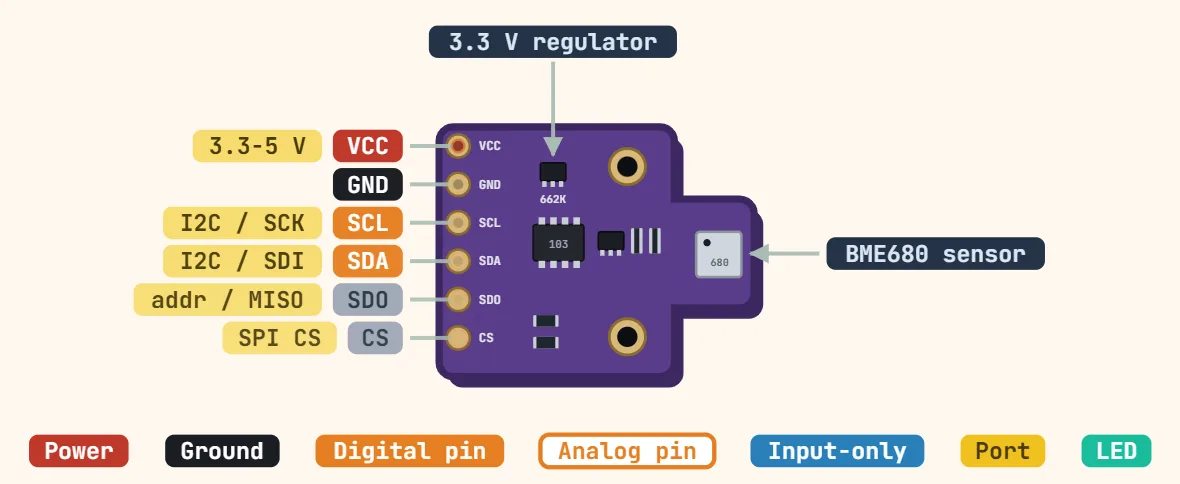 BME680 environmental sensor module (CJMCU-680)Board supply: 3.3–5 V (CJMCU-680 has a 3.3 V regulator); Chip supply: 1.71–3.6 V (VDDIO 1.2–3.6 V); Interface: I2C (up to 3.4 MHz) or SPI (up to 10 MHz)
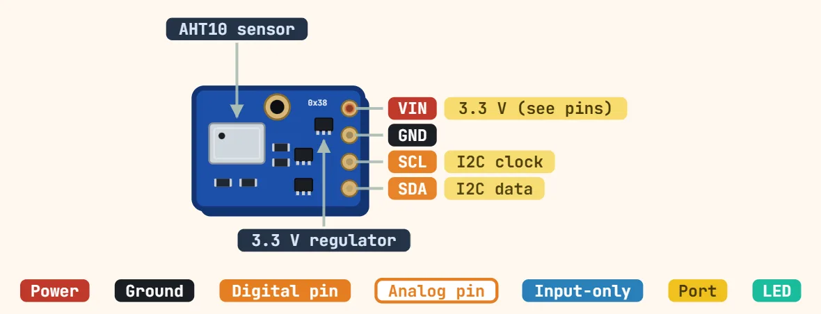 AHT10 / AHT20 temperature & humidity sensorSupply voltage: AHT20: 2.0–5.5 V; AHT10: 1.8–3.6 V; Interface: I2C; I2C address: 0x38 (fixed)
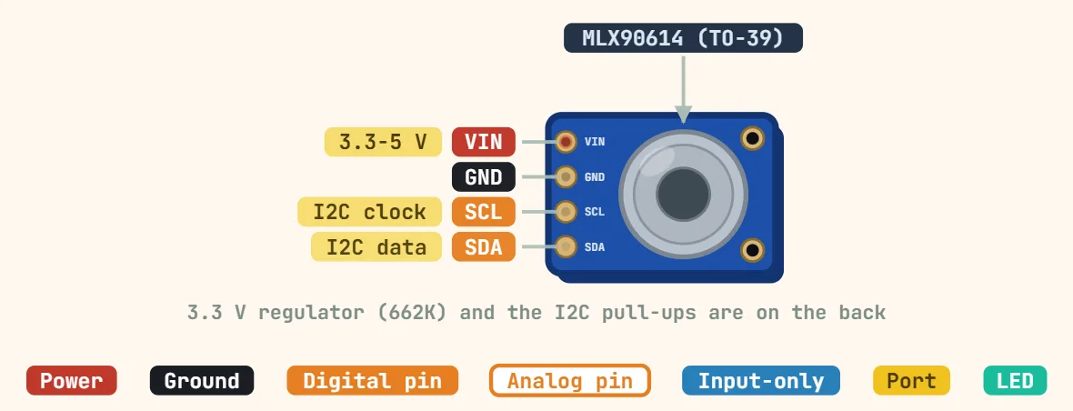 MLX90614 IR contactless temperature sensor (GY-906)Board supply: 3–5 V (GY-906 with regulator); Chip supply: 3 V grade: 2.6–3.6 V; 5 V grade: 4.5–5.5 V; Interface: SMBus/I2C up to 100 kHz, or PWM
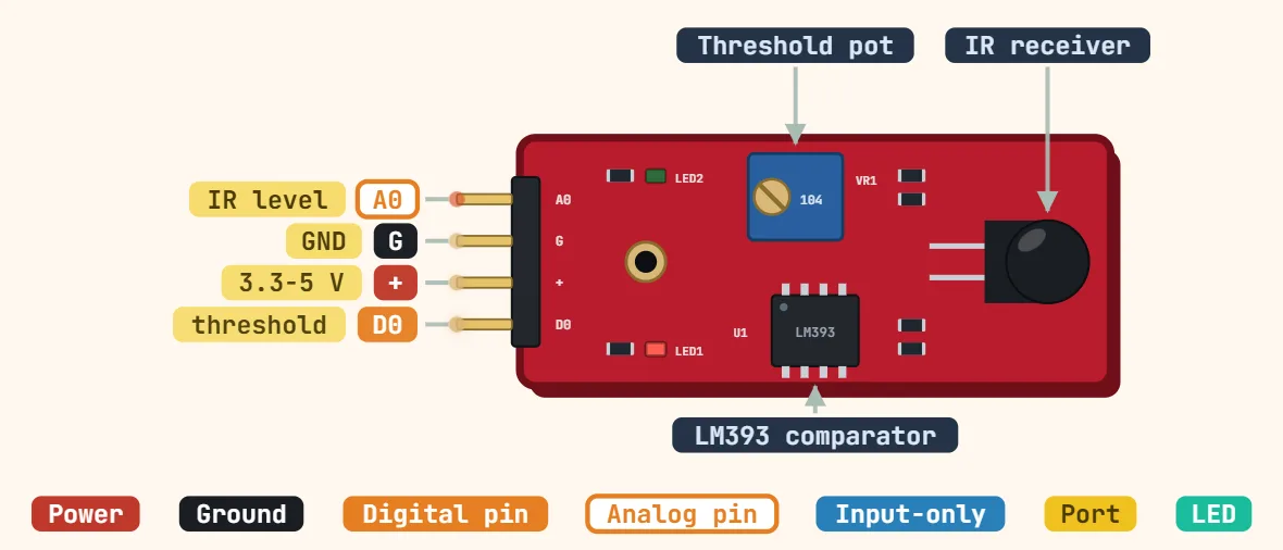 Flame sensor module (KY-026, IR)Supply voltage: 3.3–5 V (some clones 5 V only); Sensor: IR phototransistor; Spectral range: ≈760–1100 nm
Motors & actuators
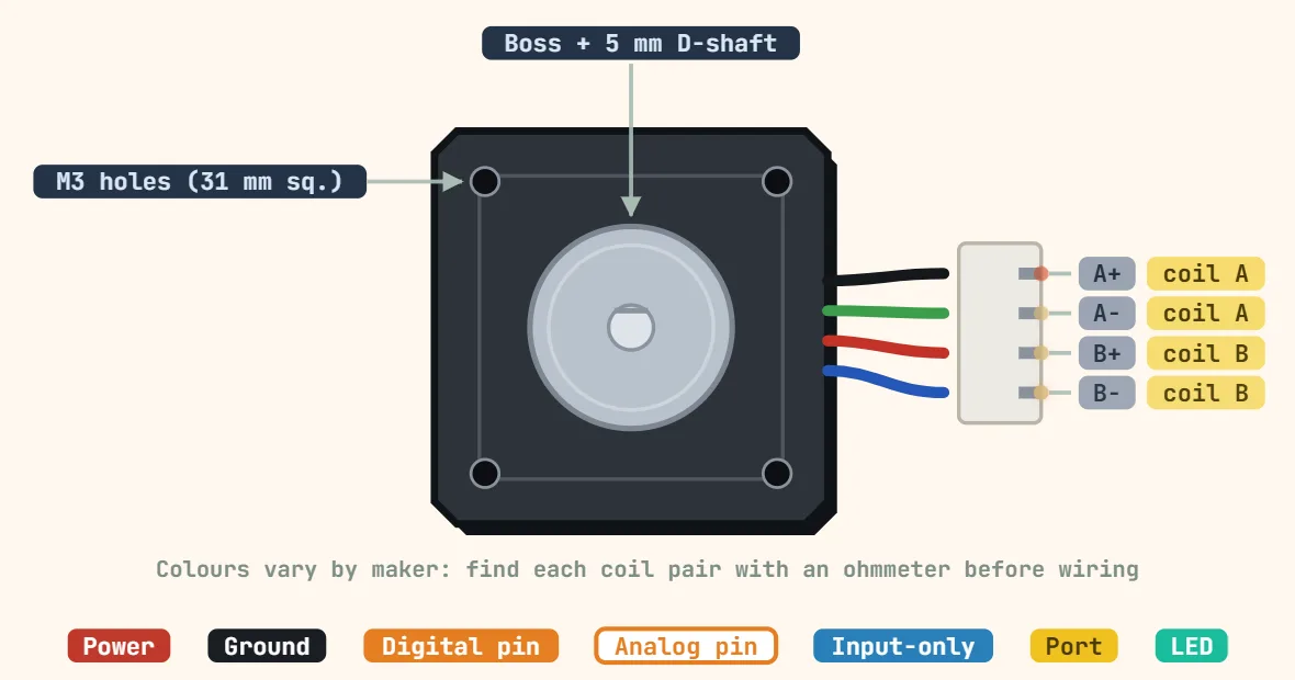 Stepper motor (NEMA 17, bipolar, 4-wire)Type: Bipolar hybrid stepper, 2 phases, 4 wires; Step angle: 1.8° (200 steps/rev) on most models; 0.9° versions exist; Rated current: Model-dependent,…
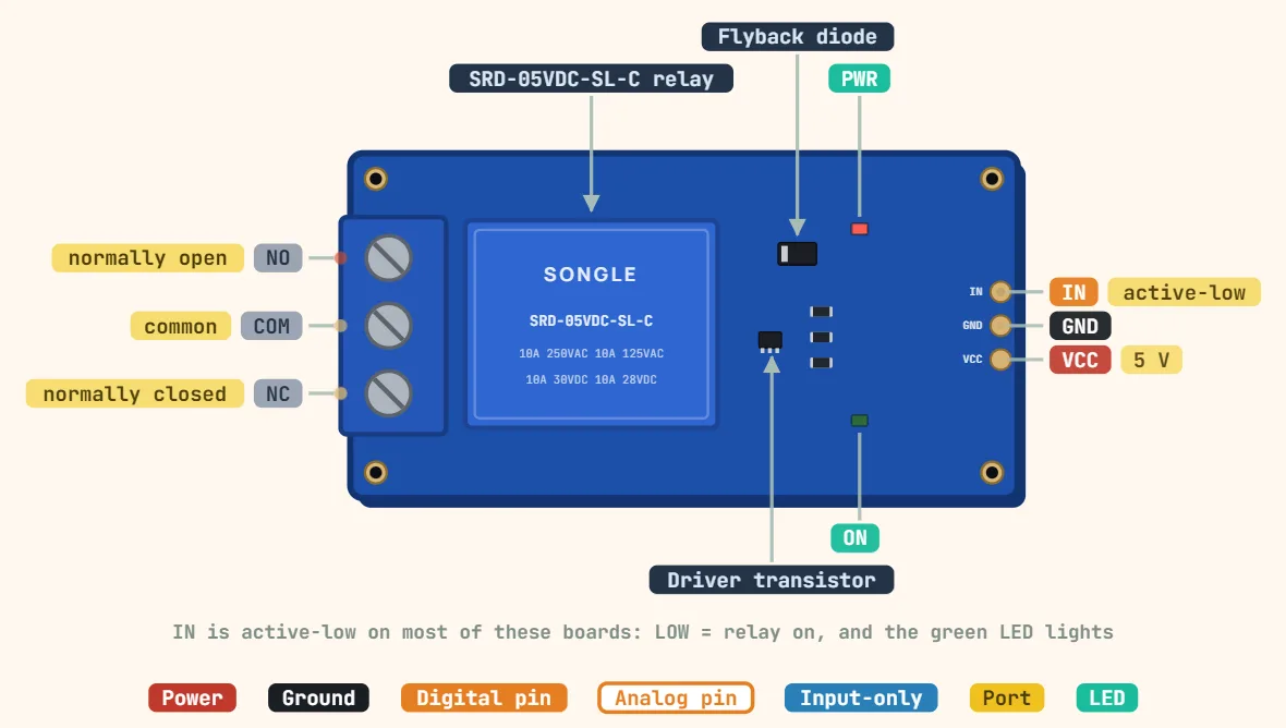 Relay module (1-channel SRD-05VDC, SPDT)Relay: SRD-05VDC-SL-C; Coil voltage: 5 V DC; Coil resistance: 70 Ω
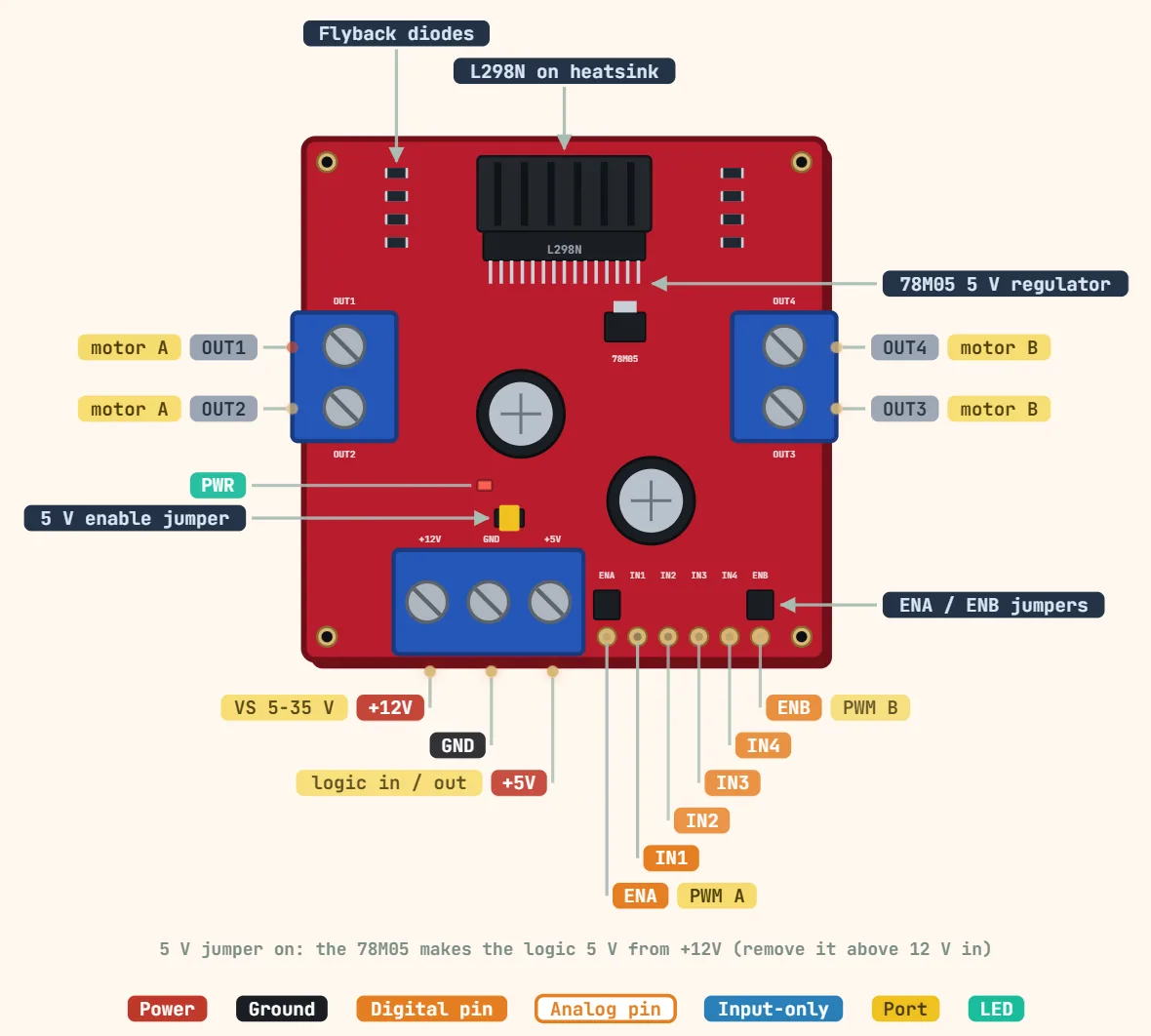 L298N motor driver moduleDriver IC: L298N dual full bridge; Motor supply (VS): 5–35 V; Logic supply: 5 V (from onboard 78M05 when the jumper is on)
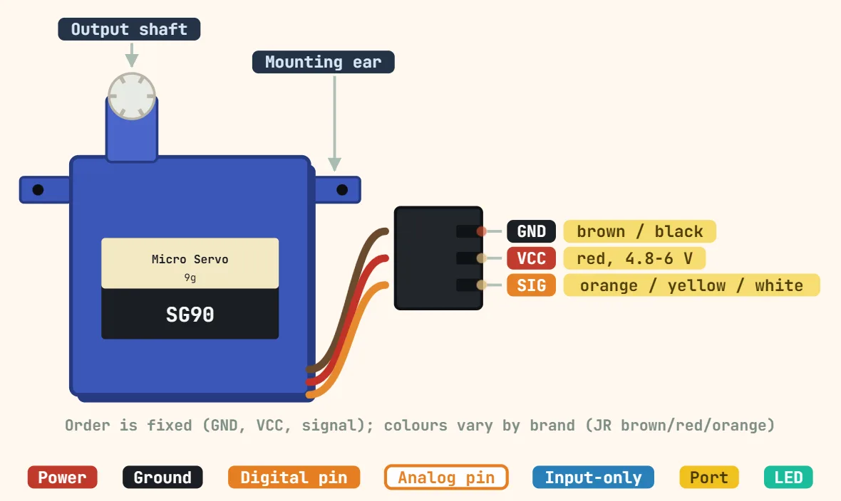 Servo motor connector (SG90, 3-pin PWM)Operating voltage: 4.8–6 V; Stall torque: 1.8 kgf·cm at 4.8 V; Speed: 0.1 s / 60° at 4.8 V
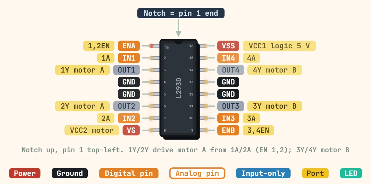 L293D motor driver (DIP-16, dual H-bridge)Logic supply (VCC1): 4.5–7 V (5 V typical); Motor supply (VCC2): VCC1 – 36 V; Output current: 600 mA per channel continuous
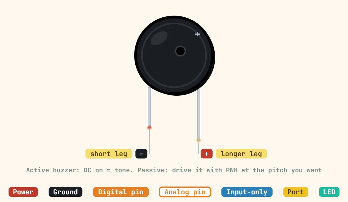 Piezo buzzer (2-pin)Type: Active (built-in oscillator, DC) or passive (needs square wave); Rated voltage: 5 V typical; 3.3 V and 12 V versions exist; Current: ≤ 30 mA (5 V…
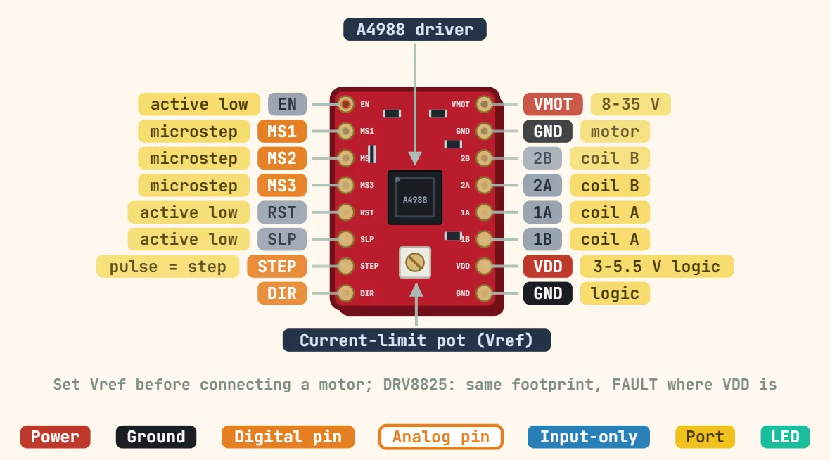 A4988 stepper driver (StepStick)Motor supply (VMOT): 8–35 V; Logic supply (VDD): 3–5.5 V; Output current: ≈1 A per phase without heatsink; 2 A max with cooling
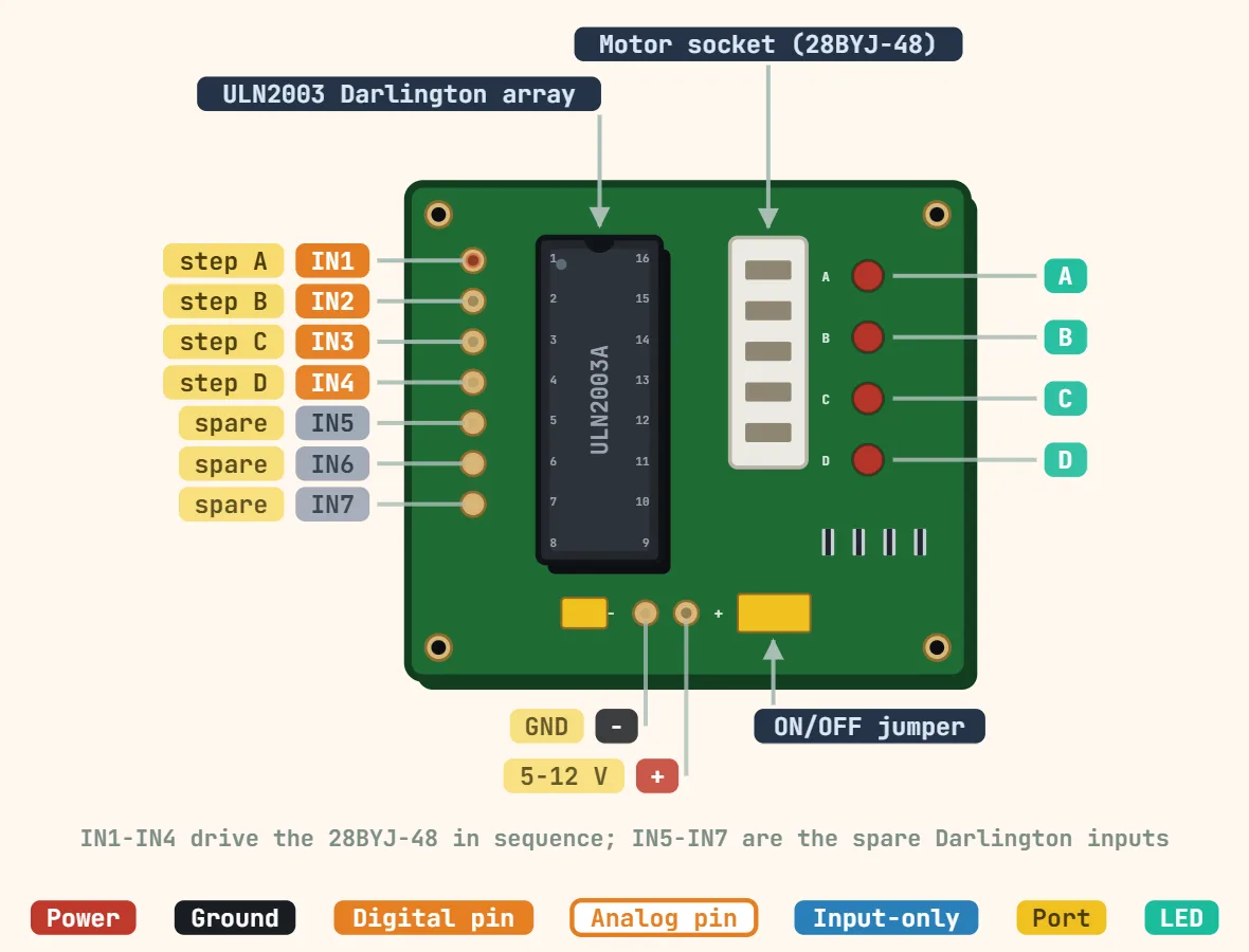 ULN2003 driver board (28BYJ-48 stepper)Driver IC: ULN2003A, 7 Darlington channels; Channel current: 500 mA max per channel; Output voltage: 50 V max
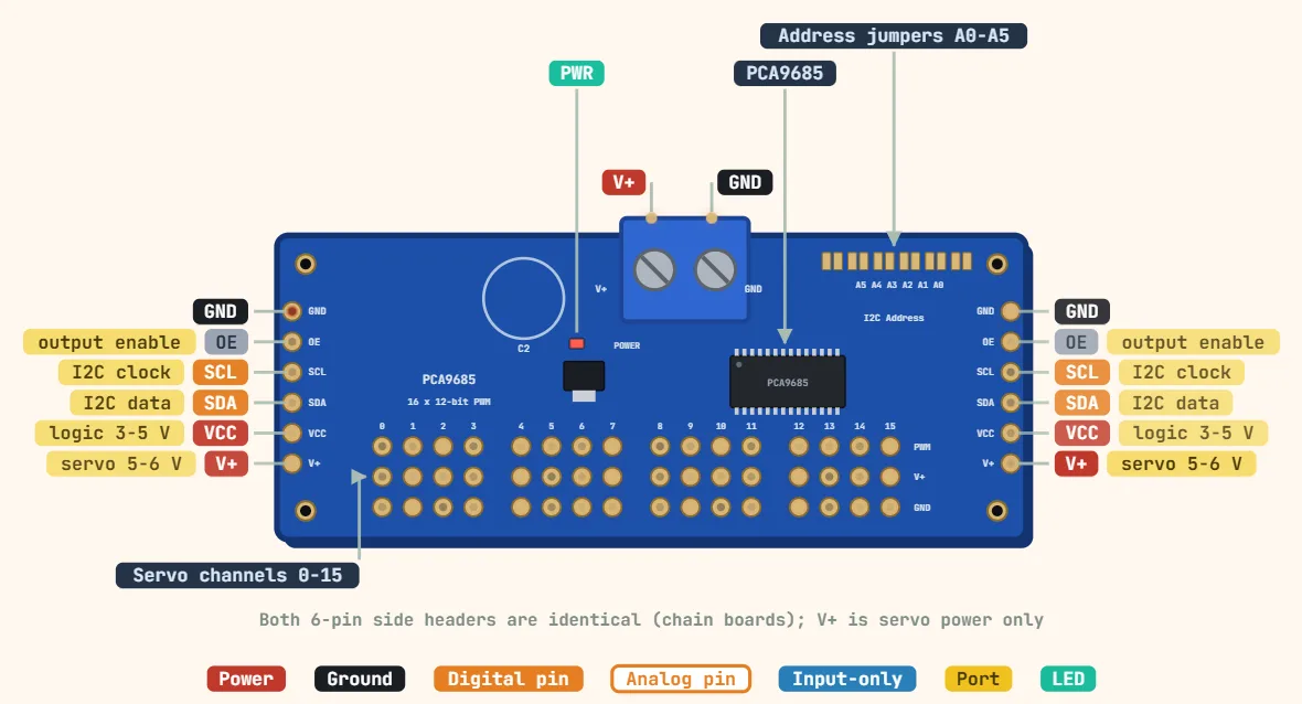 PCA9685 16-ch PWM/servo driverLogic supply (VCC): 2.3–5.5 V; Servo supply (V+): 5–6 V, separate supply; Interface: I2C, up to 1 MHz
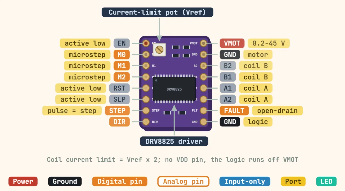 DRV8825 stepper driver (StepStick / Pololu carrier)Motor supply (VMOT): 8.2–45 V; Logic supply: None needed (internal regulator from VMOT); Logic level: 3.3 V and 5 V compatible
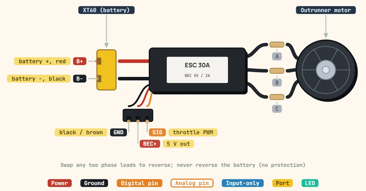 Brushless motor + ESC (3-phase, RC-style)Motor type: 3-phase BLDC, usually sensorless outrunner; Battery input: Set by the ESC rating, e.g. 2S–4S LiPo (7.4–14.8 V nominal); ESC current rating:…
Displays & LEDs
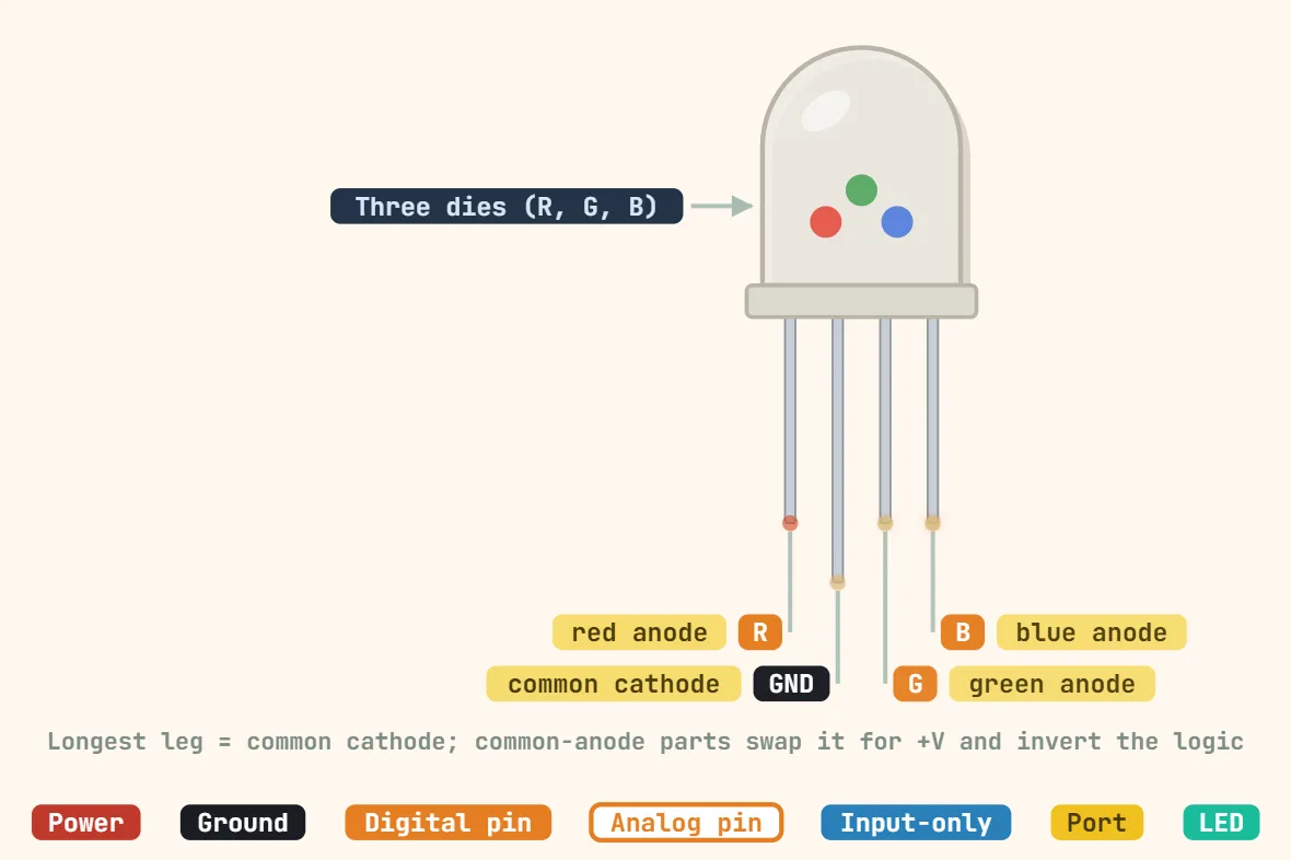 RGB LED (5 mm, common cathode, 4-pin)Package: 5 mm through-hole, 4 leads; Configuration: Common cathode (longest lead); Forward voltage (red): ≈ 2 V typical
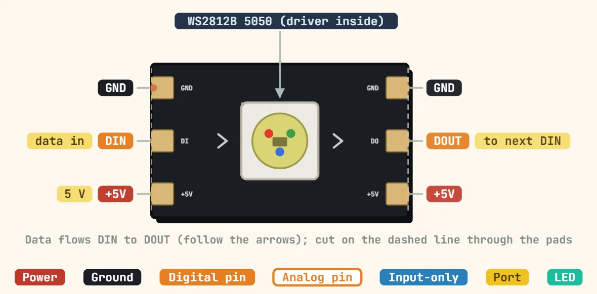 WS2812B / NeoPixel addressable LED stripLED: WS2812B, 5050 package with built-in driver; Supply voltage: 5 V (chip rated 3.5–5.3 V); Data input high: ≥ 0.7 × VDD (3.5 V at 5 V supply)
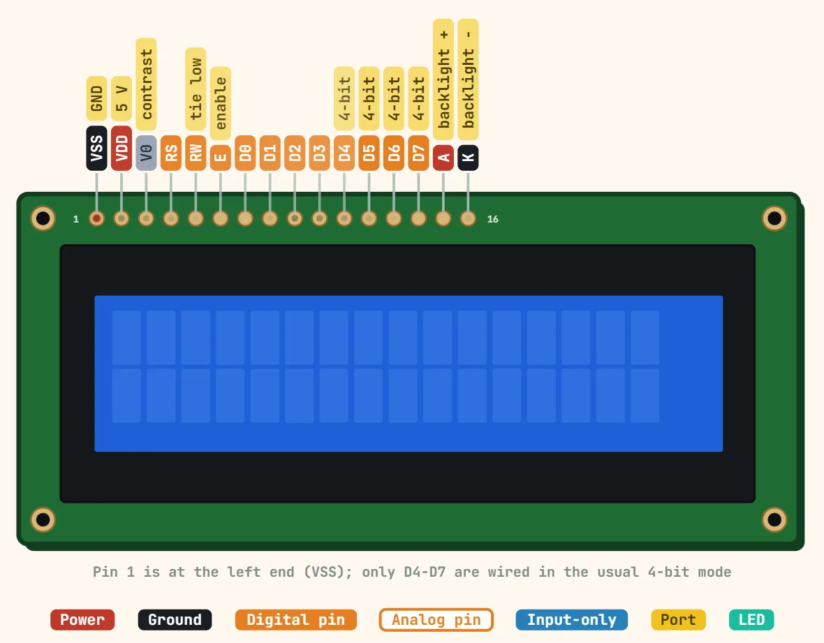 16×2 character LCD (HD44780, 16-pin)Controller: HD44780 or compatible; Display: 16 characters × 2 lines, 5 × 8 dot cells; Supply voltage: 5 V (3.3 V versions exist)
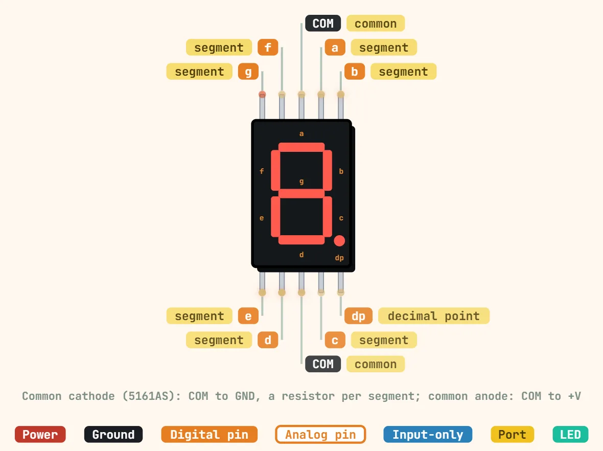 7-segment display (single digit, 10-pin)Digit height: 0.56 in (14.2 mm); Configuration: Common cathode (5161AS) or common anode (5161BS); Segments: 7 + decimal point
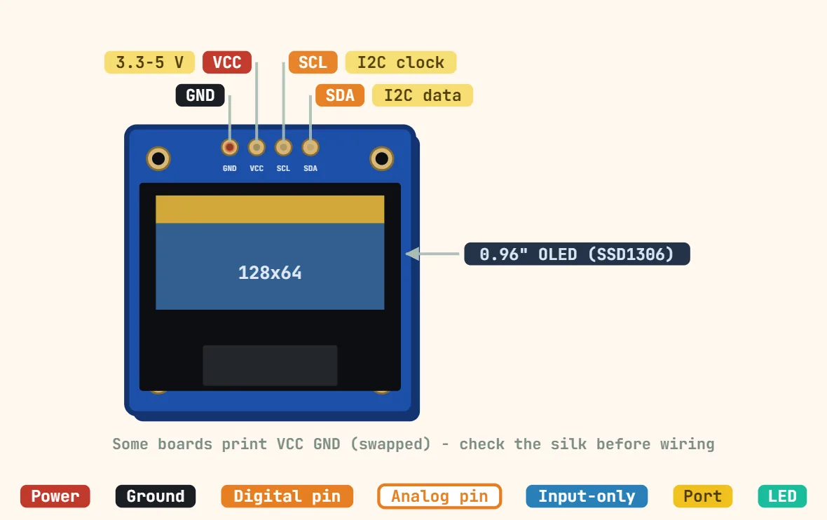 SSD1306 OLED 128×64 (0.96″, I2C, 4-pin)Controller: SSD1306; Resolution: 128 × 64 pixels, monochrome; Diagonal: 0.96 in
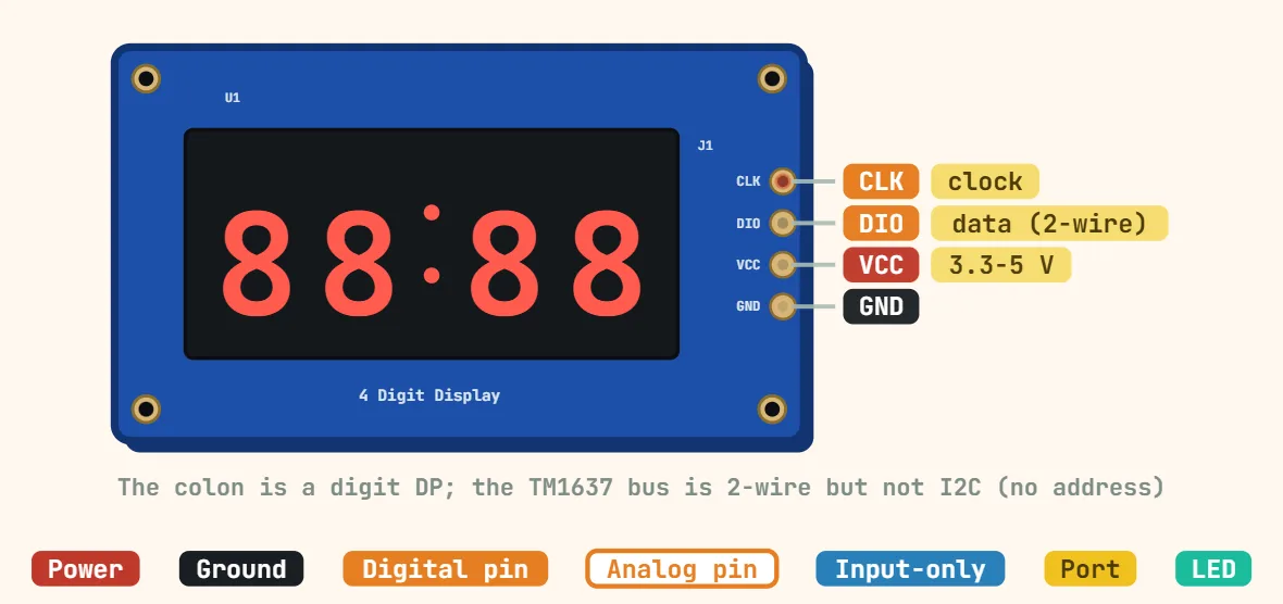 TM1637 4-digit 7-segment moduleDriver IC: TM1637; Digits: 4 × 7-segment with centre colon; Supply voltage: 3.3–5 V (module)
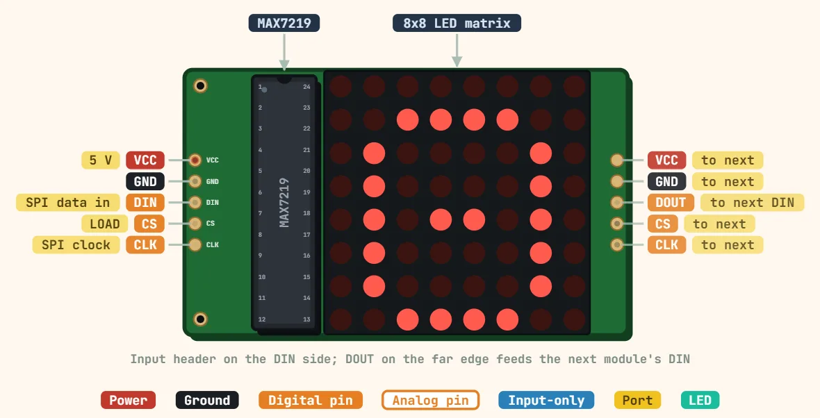 MAX7219 8×8 LED matrix moduleDriver IC: MAX7219; Display: 8 × 8 LEDs (64), single colour; Supply voltage: 5 V (IC rated 4.0–5.5 V)
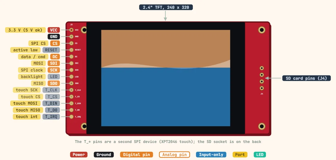 ILI9341 TFT display (SPI, 2.4″)Controller: ILI9341; Resolution: 240 × 320 pixels; Colour depth: Up to 262K colours (18-bit); 16-bit RGB565 typical
Wireless & communication
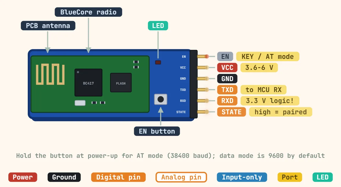 HC-05 / HC-06 Bluetooth serial module (ZS-040)Bluetooth: v2.0 + EDR, Classic SPP (no BLE); Role: HC-05 master/slave; HC-06 slave only; Frequency: 2.4 GHz
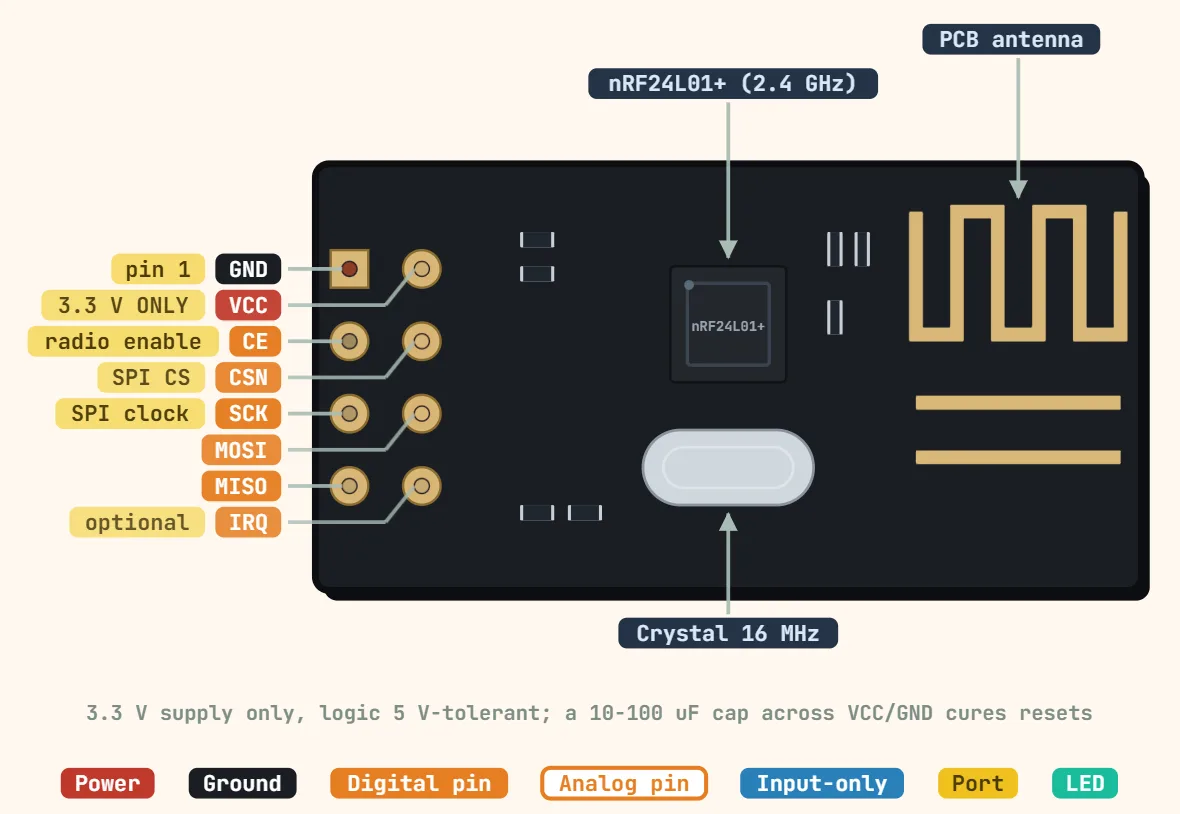 NRF24L01 2.4GHz radio (2×4 header)Chip: Nordic nRF24L01+; Supply voltage: 1.9–3.6 V (use 3.3 V); Logic inputs: 5 V tolerant
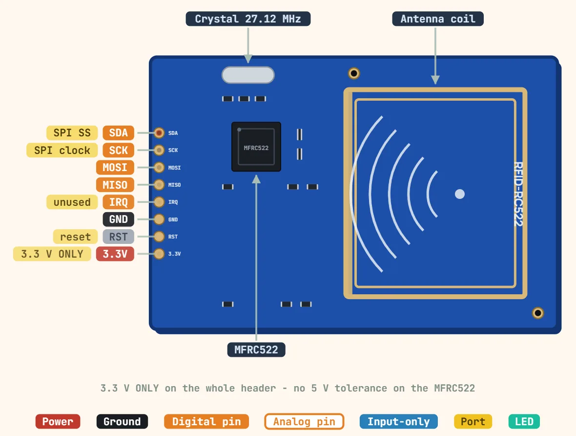 RFID-RC522 reader (SPI)Chip: NXP MFRC522; Frequency: 13.56 MHz; Supported cards: ISO/IEC 14443 A, MIFARE Classic/Ultralight
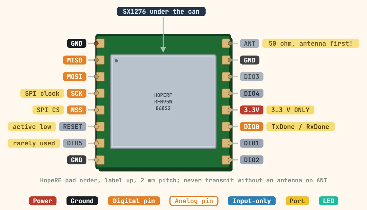 LoRa module (RFM95W / SX1276-family)Transceiver: Semtech SX1276 (RFM95W); Frequency: 868 / 915 MHz (RFM95W); 433 MHz on RFM96/98W; Supply voltage: 1.8–3.7 V (no onboard regulator)
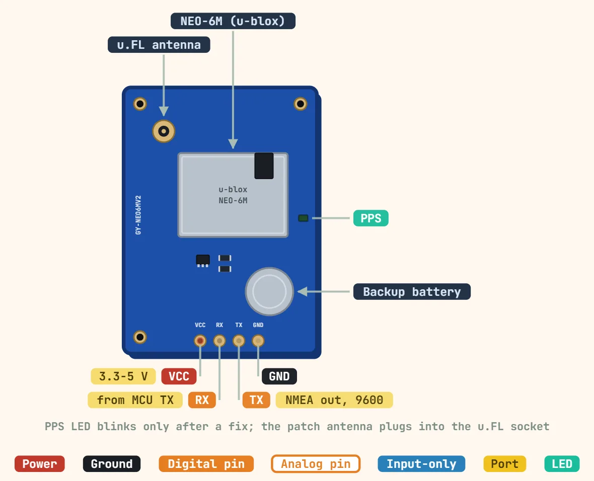 GPS NEO-6M module (GY-NEO6MV2)Receiver: u-blox NEO-6M; Signal: GPS L1, 1575.42 MHz; Channels: 50
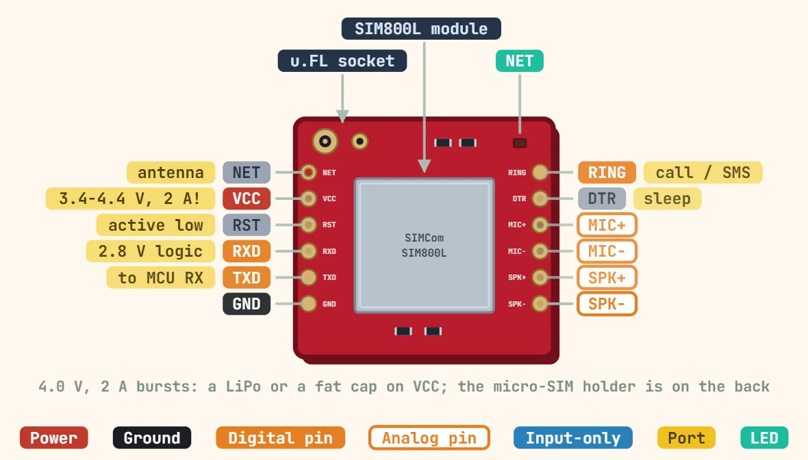 SIM800L GSM moduleNetwork: 2G only: GSM/GPRS quad-band 850/900/1800/1900 MHz; Supply voltage: 3.4–4.4 V (≈ 4.0 V ideal, not 5 V); Peak current: Up to 2 A transmit bursts
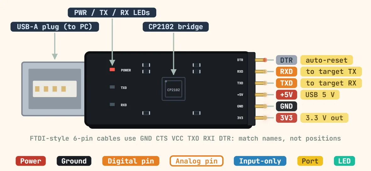 CP2102 / CH340 USB-to-serial adapter (6-pin)Chip: Silicon Labs CP2102 or WCH CH340; USB: USB 2.0 full speed (12 Mbit/s); Baud rate: CP2102: 300 bps–1 Mbps; CH340: 50 bps–2 Mbps
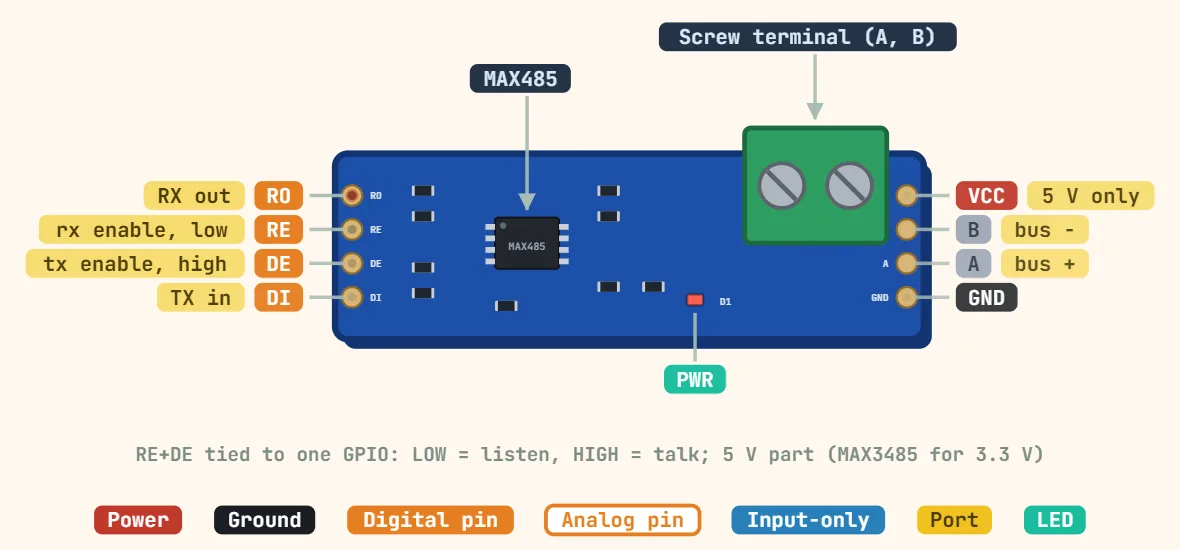 MAX485 RS-485 transceiver module (8-pin breakout board)Transceiver: MAX485; Supply voltage: 5 V (4.75–5.25 V); Logic level: 5 V (use MAX3485/SP3485 for 3.3 V)
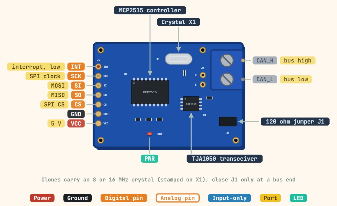 CAN bus transceiver module (MCP2515 + TJA1050)Controller: Microchip MCP2515 (CAN 2.0B); Transceiver: NXP TJA1050; Supply voltage: 5 V (TJA1050 is 5 V only)
Connectors
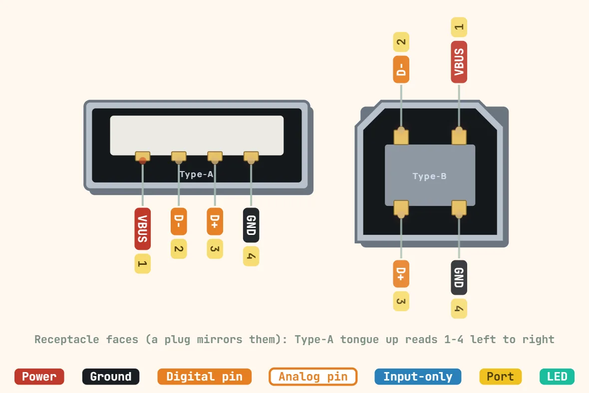 USB Type-A / Type-BContacts: 4 (USB 2.0), 9 (USB 3.x); Bus voltage: 5 V; Current (standard port): 500 mA (USB 2.0), 900 mA (USB 3.x)
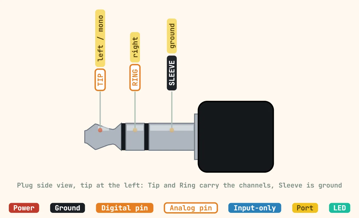 3.5mm audio jack (TRS)Contacts: 2 (TS), 3 (TRS), 4 (TRRS); Plug diameter: 3.5 mm; Stereo pinout: Tip left, ring right, sleeve ground
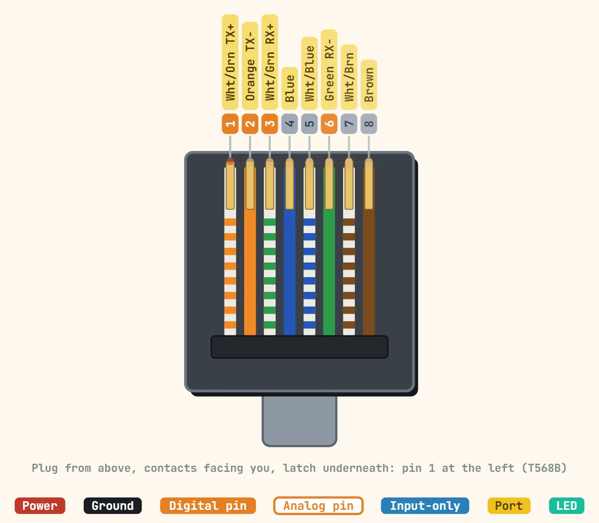 Ethernet (RJ45, T568B)Contacts: 8 (8P8C); Contact pitch: 1.02 mm; Pairs used: 2 pairs (10/100BASE-T, pins 1-2, 3-6), 4 pairs (1000BASE-T)
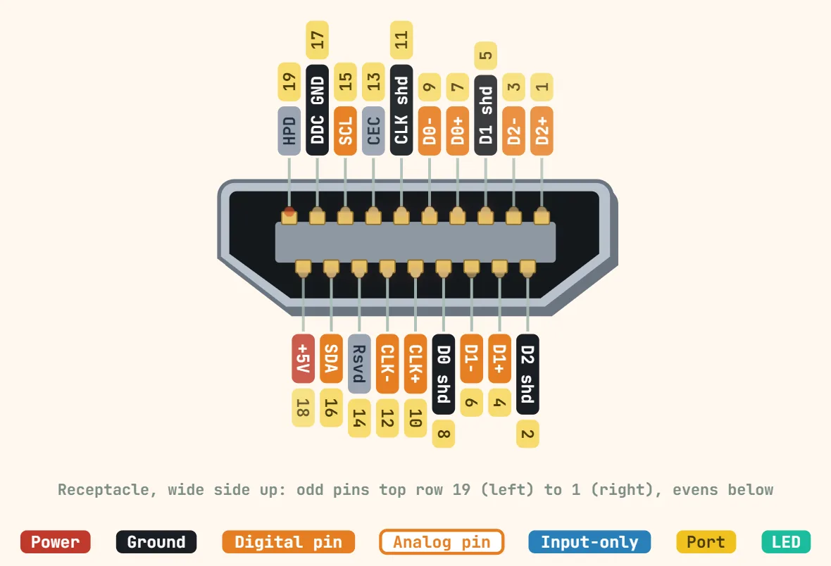 HDMI (Type A, 19 pins)Contacts: 19; Video signals: 3 TMDS data pairs + 1 clock pair; Max bandwidth: 10.2 Gbit/s (1.3/1.4), 18 Gbit/s (2.0), 48 Gbit/s (2.1)
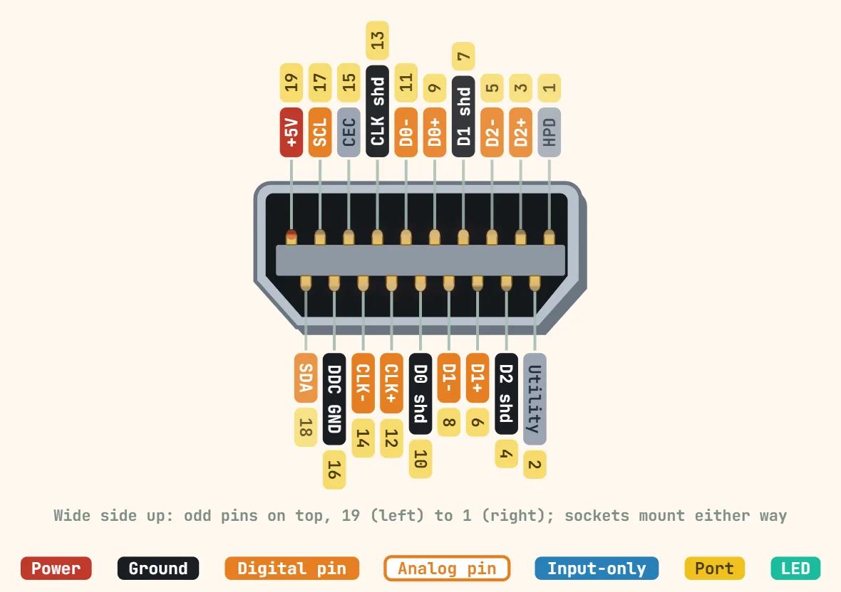 Micro-HDMI (Type D, 19 pins)Contacts: 19 (numbered differently from Type A); Contact pitch: 0.4 mm; Plug size: ≈ 6.4 × 2.8 mm
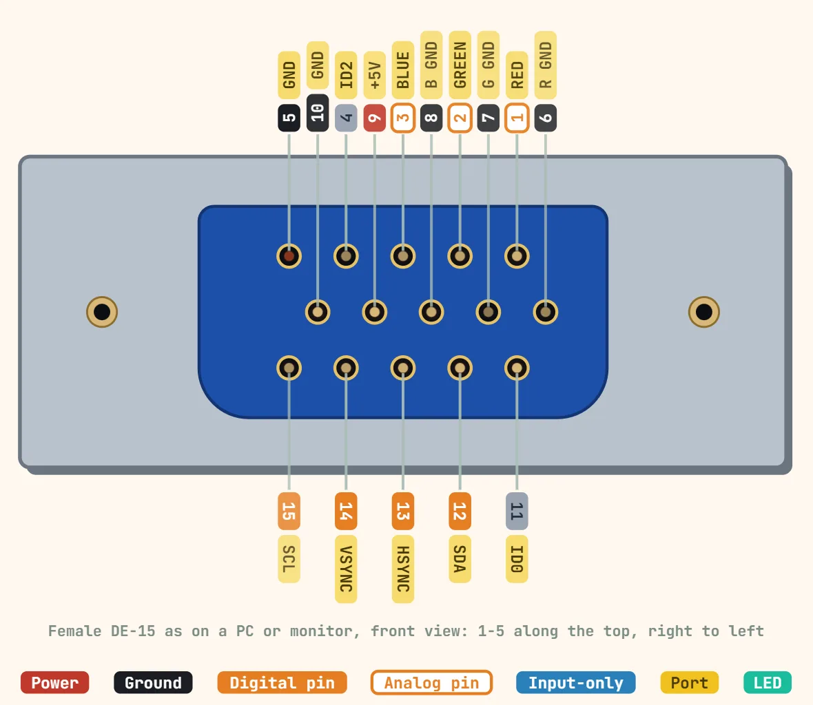 VGA (DE-15)Contacts: 15 in 3 rows (DE-15 high density); Video signals: Analog R, G, B, 0.7 V peak-to-peak into 75 Ω; Sync: Separate H and V sync, TTL level
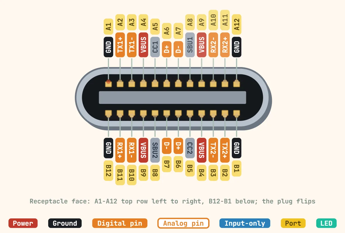 USB-C (receptacle, key pins)Contacts: 24 (receptacle); Contact pitch: 0.5 mm; Plug size: 8.25 × 2.4 mm, reversible
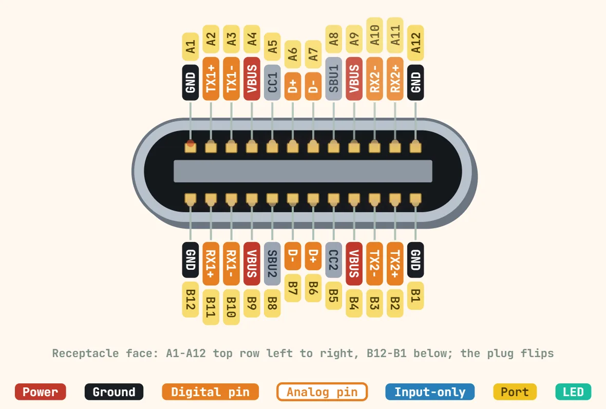 USB Type-C (USB-PD capable receptacle)Contacts: 24 (receptacle); Default VBUS: 5 V until a PD contract is negotiated; PD fixed voltages (SPR): 5, 9, 15, 20 V
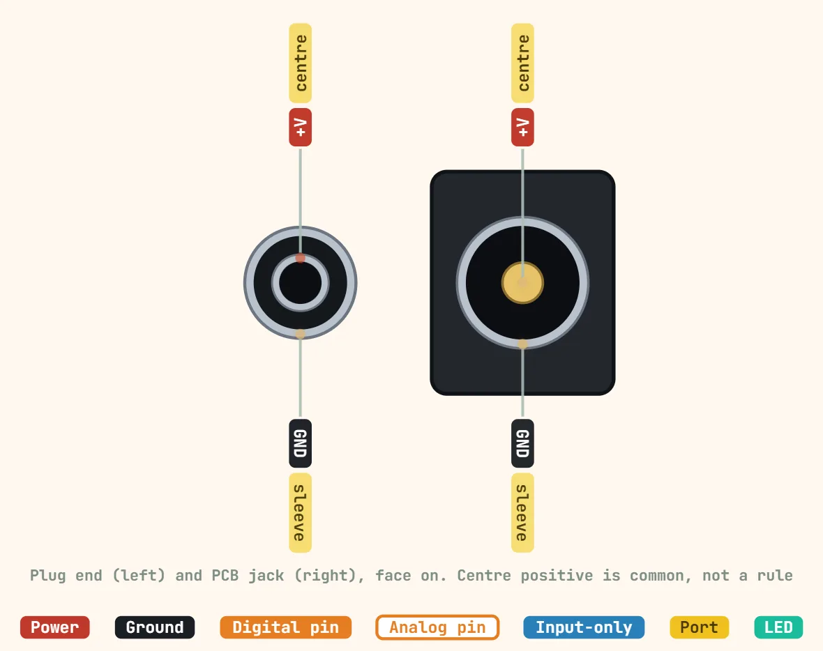 DC barrel jack (5.5×2.1mm)Contacts: 2 (centre pin, sleeve) + often a switch contact; Plug outer diameter: 5.5 mm; Centre pin diameter: 2.1 mm
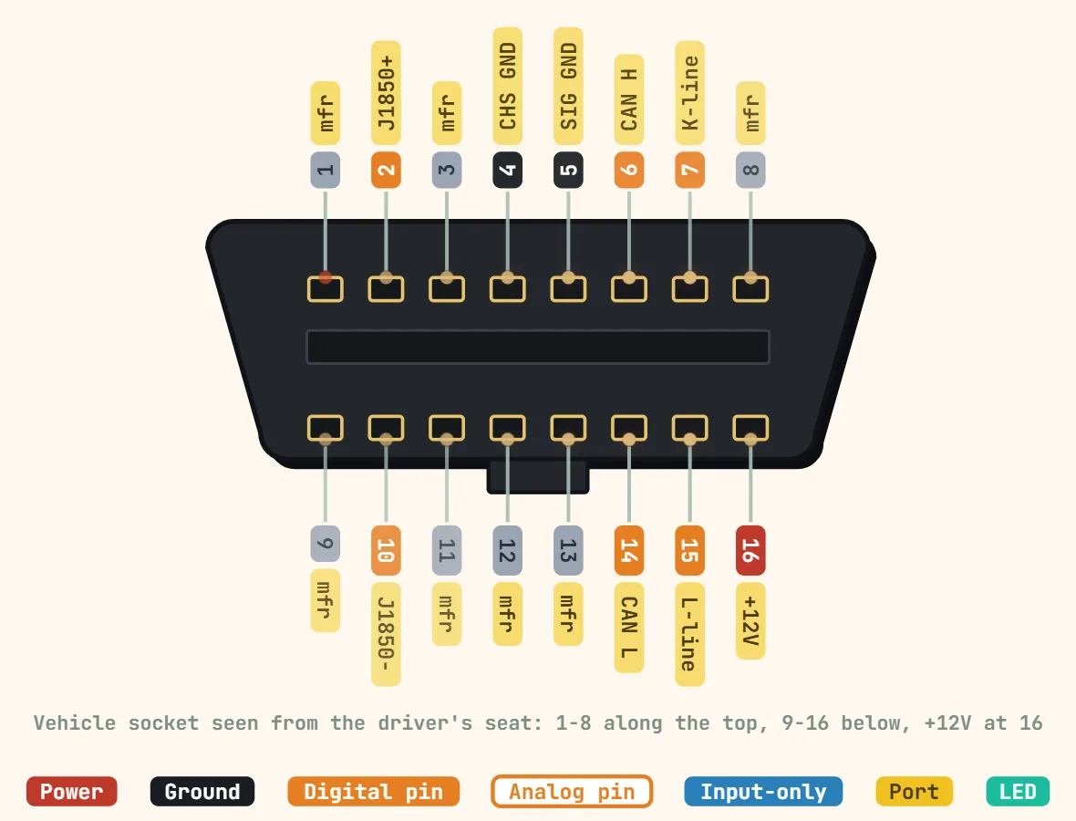 OBD-II diagnostic connector (SAE J1962, 16-pin)Contacts: 16 (2 rows of 8); Standard: SAE J1962 / ISO 15031-3; Supply: Pin 16, battery voltage: 12 V (Type A), 24 V (Type B)
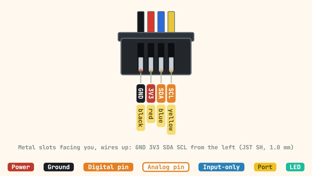 Qwiic / STEMMA QT connector (4-pin, I2C)Contacts: 4; Connector: JST SH, polarized; Pitch: 1.0 mm
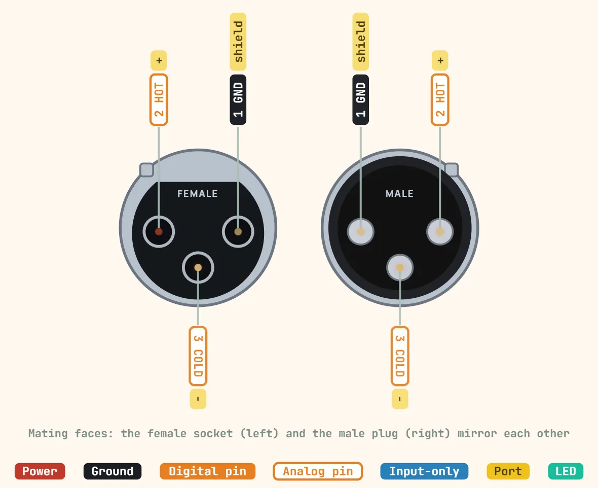 XLR (3-pin, balanced audio)Contacts: 3; Pinout: 1 shield, 2 hot (+), 3 cold (−) per AES14 / IEC 60268-12; Signal: Balanced, differential
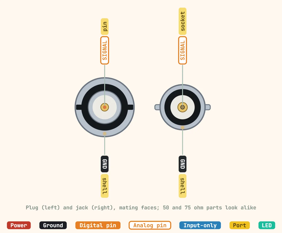 BNC connectorContacts: 2 (centre pin, shell); Impedance: 50 Ω (test gear, RF) or 75 Ω (video, SDI); Coupling: Quarter-turn bayonet
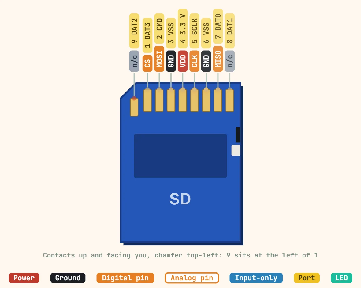 SD card (SPI mode)Contacts: 9 (SD), 8 (microSD); Supply: 2.7–3.6 V; Logic level: 3.3 V, not 5 V tolerant
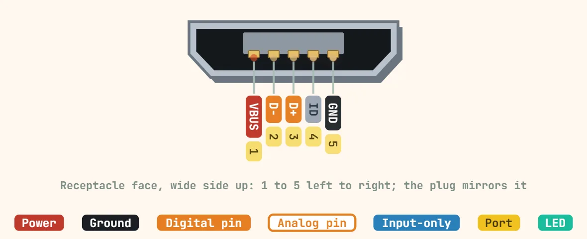 Micro-USB (5-pin)Contacts: 5 (USB 2.0 Micro-B), 10 (USB 3.0 Micro-B); Contact pitch: 0.65 mm; Plug size: 6.85 × 1.8 mm
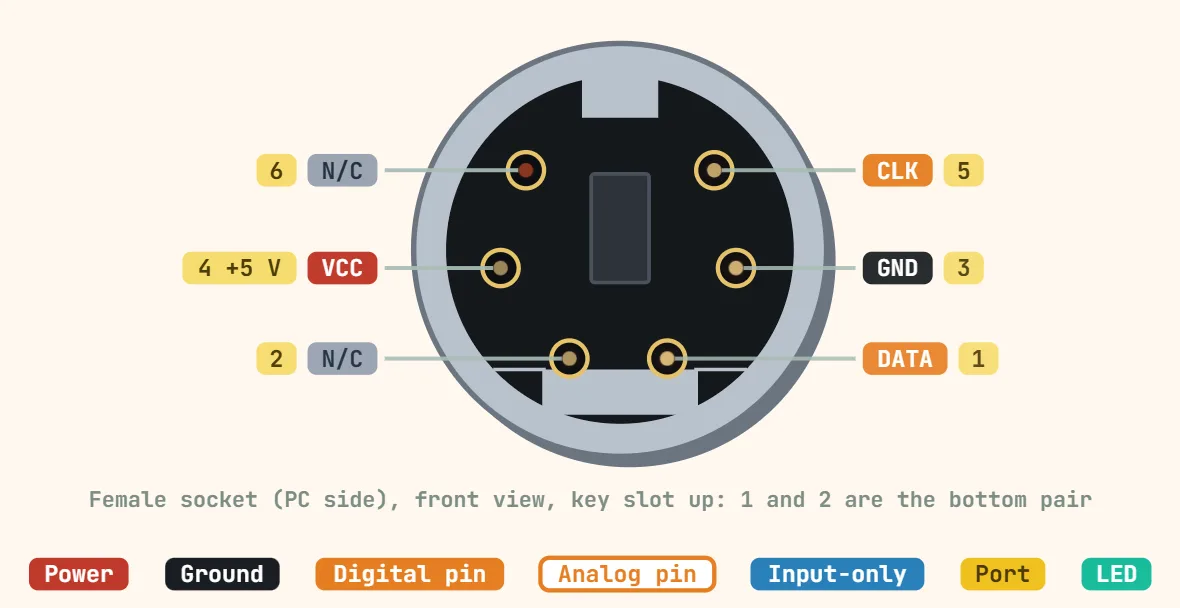 PS/2 connector (6-pin mini-DIN)Contacts: 6 (4 used); Supply: 5 V; Clock: Generated by the device, 10–16.7 kHz
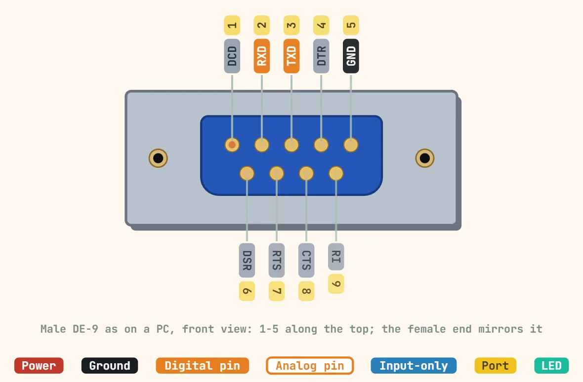 RS-232 (DE-9 / DB9)Contacts: 9 (DE-9); Standard: TIA-232-F; Logic 1 (mark): −3 to −15 V
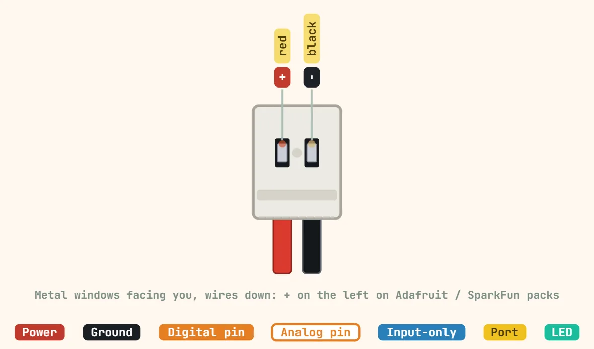 2-pin JST battery connectorContacts: 2; JST-PH pitch: 2.0 mm; JST-PH rating: 2 A, 100 V
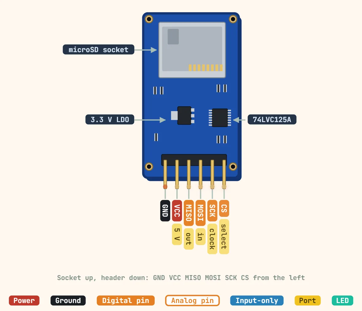 MicroSD card module (SPI)Pins: 6: GND, VCC, MISO, MOSI, SCK, CS; Supply: 5 V (regulated modules), 3.3 V (bare boards); Card logic: 3.3 V, level shifted on 5 V modules
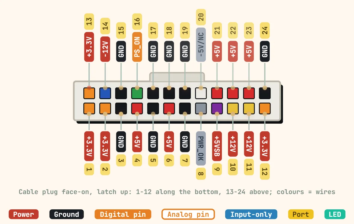 ATX PSU 24-pin motherboard connector (ATX12V 2.x)Contacts: 24 (2 × 12), older boards 20; Connector: Molex Mini-Fit Jr; Pitch: 4.2 mm
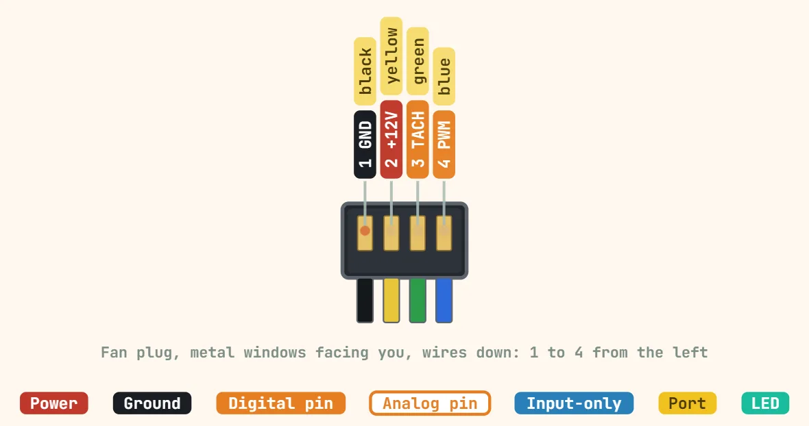 PC fan connector (4-pin PWM, Intel 4-wire)Contacts: 4; Pitch: 2.54 mm; Supply: 12 V
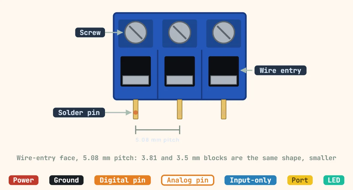 Screw terminal block (2/3/5.08mm pitch)Common pitches: 2.54, 3.5, 3.81, 5.0, 5.08 mm; 2.54 mm (typical): 6–8 A, 130–150 V, 18–26 AWG; 3.5 / 3.81 mm (typical): 8–10 A, 250–300 V, 16–28 AWG
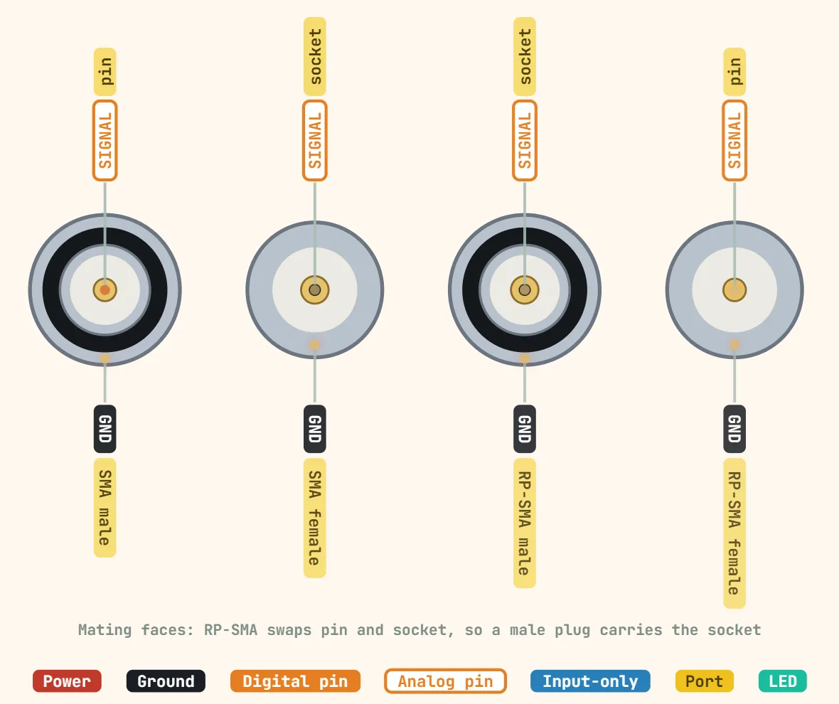 SMA connectorImpedance: 50 Ω; Frequency range: DC–18 GHz; Thread: 1/4"-36 UNS
Buses & debug
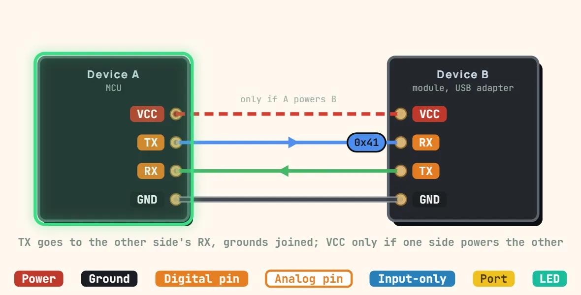 UART (TTL, 4 pins)Signals: TX, RX, GND (VCC optional); Topology: Point-to-point, TX crossed to RX; Duplex: Full duplex
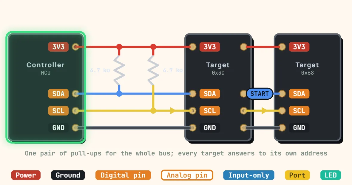 I2C (bus)Signals: SDA, SCL + GND; Topology: Multi-drop bus, multi-controller capable; Duplex: Half duplex
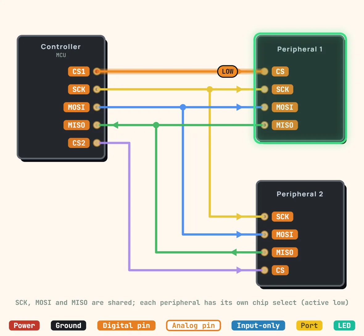 SPI (standard 4-wire)Signals: SCK, MOSI, MISO, CS (one CS per peripheral); Topology: One controller, several peripherals sharing SCK / MOSI / MISO; Duplex: Full duplex,…
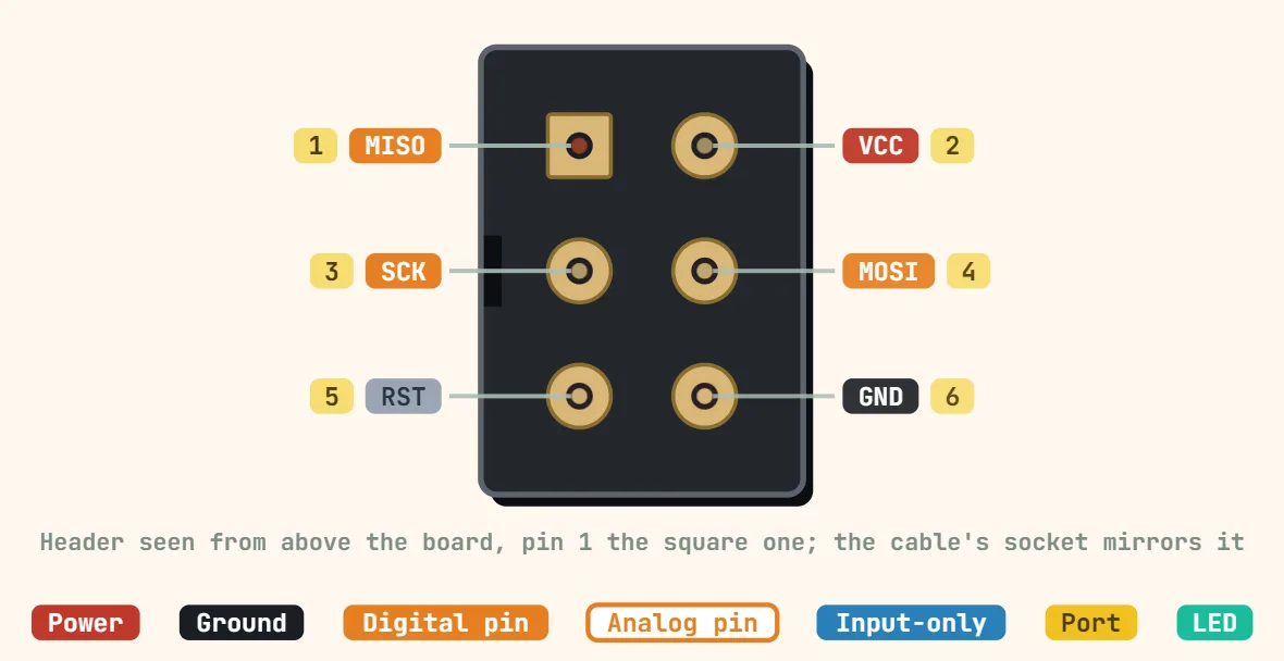 AVR ISP (2×3, 6 pins)Contacts: 6 (2 × 3); Pitch: 2.54 mm; Signals: MISO, MOSI, SCK, RESET, VCC, GND
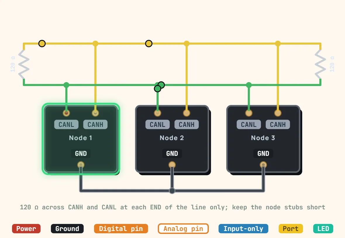 CAN bus (2-wire differential)Signals: CAN_H, CAN_L + common GND; Topology: Linear multi-drop bus, multi-master with arbitration; Duplex: Half duplex
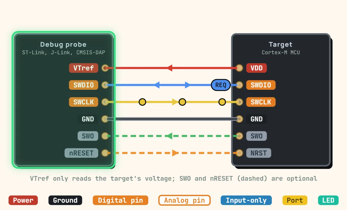 SWD debug (2-wire, ARM Cortex-M)Signals: SWDIO, SWCLK + GND, VTref; Optional: nRESET, SWO trace; Topology: Point-to-point (one probe, one target)
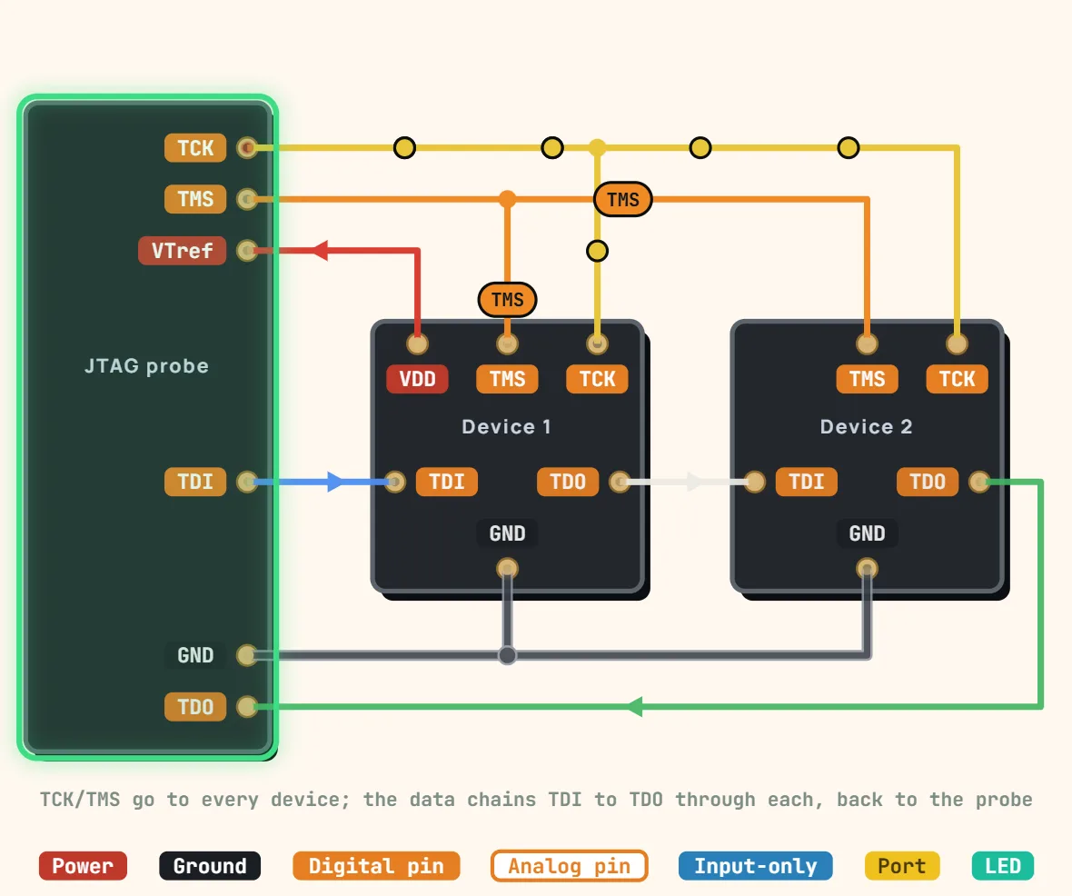 JTAG (4-wire debug, common subset)Standard: IEEE 1149.1; Signals: TCK, TMS, TDI, TDO (+ optional TRST); Topology: Daisy chain on TDI → TDO, TCK / TMS shared
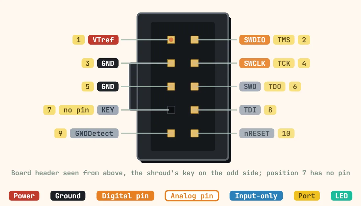 ARM Cortex Debug connector (10-pin, 1.27mm)Contacts: 10 (2 × 5), pin 7 removed as key; Pitch: 1.27 mm; Protocols: SWD, JTAG, SWO trace
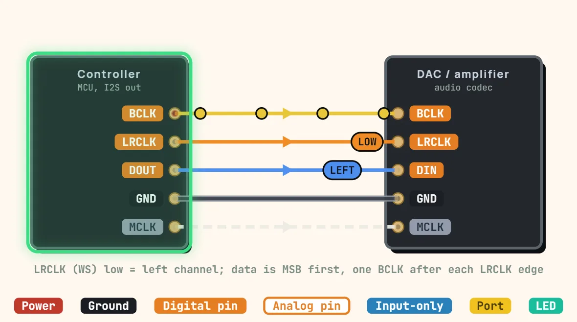 I2S (digital audio bus)Signals: BCLK, LRCLK / WS, data in / out (+ optional MCLK); Topology: Point-to-point, controller drives the clocks; Clock: Synchronous, BCLK = sample…
Logic & microcontroller ICs
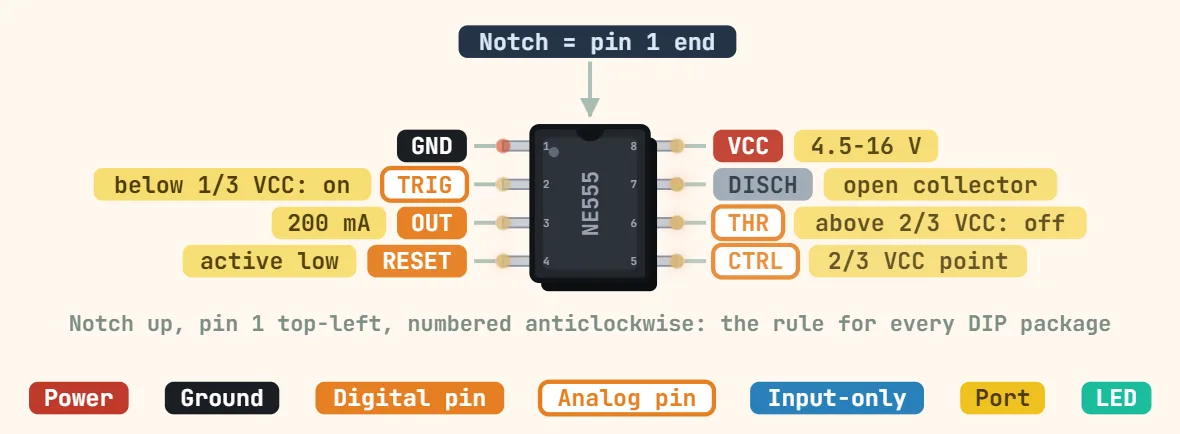 555 timer (DIP-8)Supply voltage: NE555: 4.5–16 V; CMOS TLC555: 2–15 V; ICM7555: 2–18 V; Supply current (no load): NE555: ≈ 3 mA typ at 5 V, ≈ 10 mA at 15 V; CMOS…
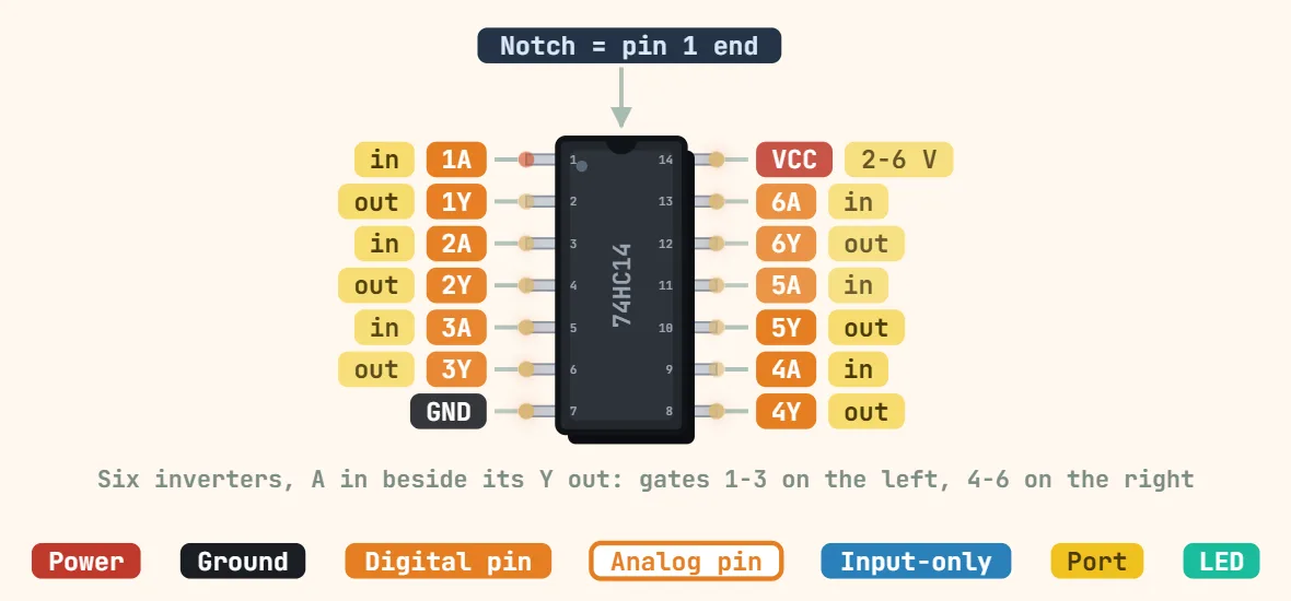 74HC14 hex Schmitt-trigger inverter (DIP-14)Logic family: 74HC (high-speed CMOS); Gates: 6 Schmitt-trigger inverters; Supply voltage: 2–6 V
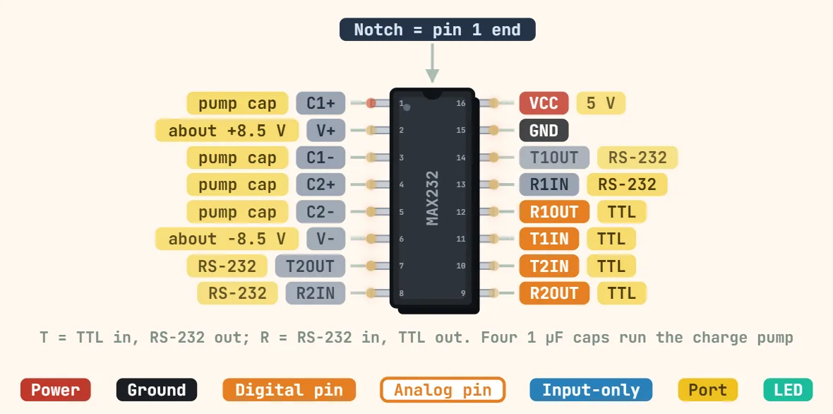 MAX232 RS-232 line driver (DIP-16)Supply voltage: 4.5–5.5 V (single 5 V supply); Supply current: ≈ 8 mA typ (no load); Channels: 2 drivers + 2 receivers
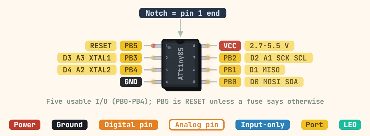 ATtiny85 (DIP-8)Core: 8-bit AVR; Supply voltage: ATtiny85: 2.7–5.5 V; ATtiny85V: 1.8–5.5 V; Clock speed: Up to 10 MHz at 2.7–5.5 V, 20 MHz at 4.5–5.5 V; internal 8 MHz…
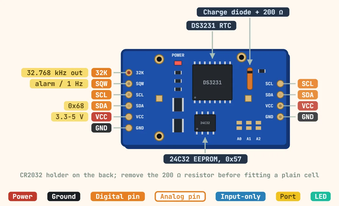 DS3231 RTC module (ZS-042, I2C)Supply voltage: Chip: 2.3–5.5 V; module typically used at 3.3–5 V; Interface: I2C, up to 400 kHz; I2C address: 0x68 (RTC); 0x57 for the on-board AT24C32…
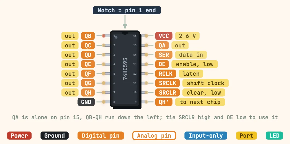 74HC595 shift register (DIP-16)Logic family: 74HC (high-speed CMOS); Function: 8-bit serial-in, parallel-out with output latch and 3-state outputs; Supply voltage: 2–6 V
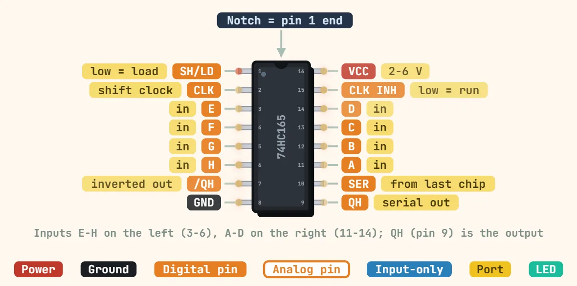 74HC165 parallel-in shift register (DIP-16)Logic family: 74HC (high-speed CMOS); Function: 8-bit parallel-in, serial-out (QH plus inverted QH output); Supply voltage: 2–6 V
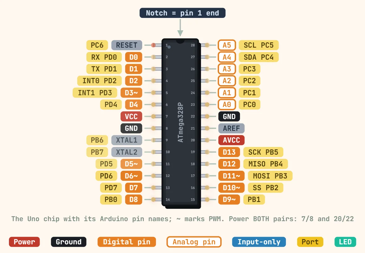 ATmega328P (DIP-28)Core: 8-bit AVR; Supply voltage: 1.8–5.5 V; Clock speed: Up to 4 MHz at 1.8 V, 10 MHz at 2.7 V, 20 MHz at 4.5–5.5 V; internal 8 MHz RC oscillator
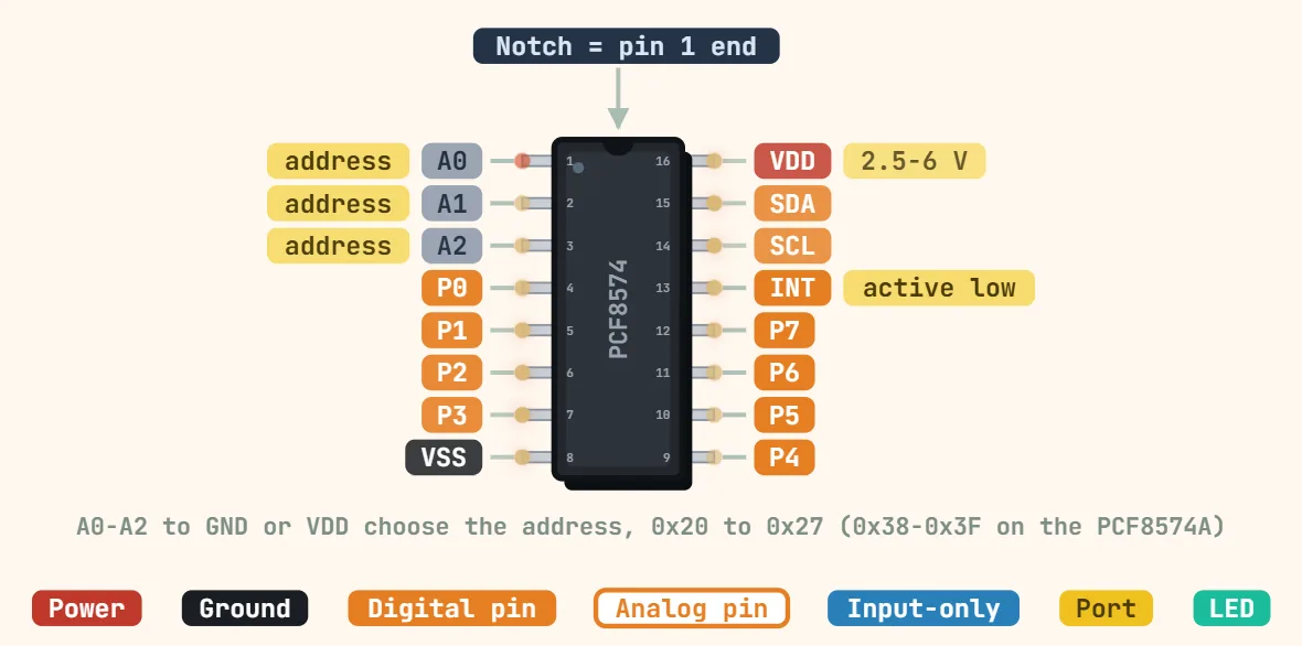 PCF8574 I2C port expander (DIP-16)Supply voltage: 2.5–6 V; Interface: I2C, 100 kHz (standard mode); I2C address: PCF8574: 0x20–0x27; PCF8574A: 0x38–0x3F (set by A0–A2)
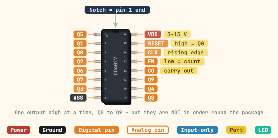 CD4017 decade counter (DIP-16)Logic family: CD4000 series CMOS; Supply voltage: 3–18 V; Max clock frequency: ≈ 5 MHz typ at 10 V (lower at 5 V)
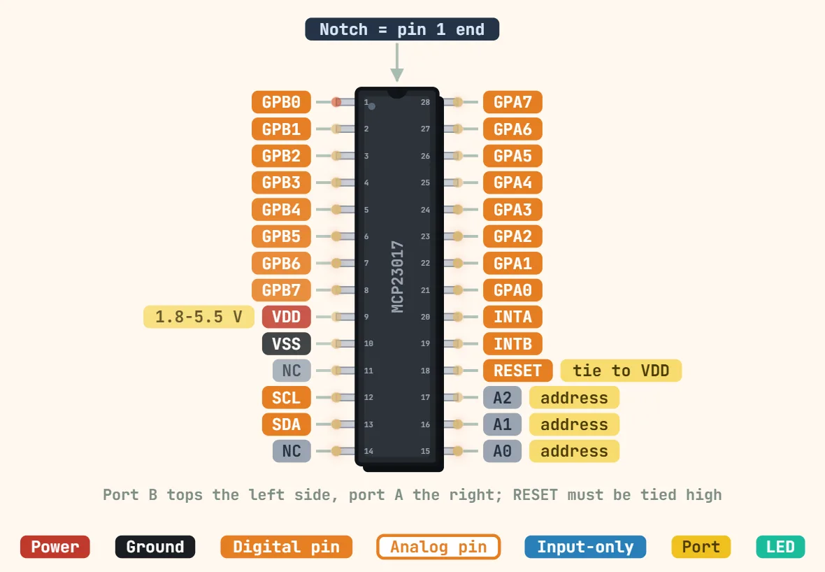 MCP23017 I2C GPIO expanderSupply voltage: 1.8–5.5 V; Interface: I2C: 100 kHz, 400 kHz, 1.7 MHz; I2C address: 0x20–0x27 (set by A0–A2)
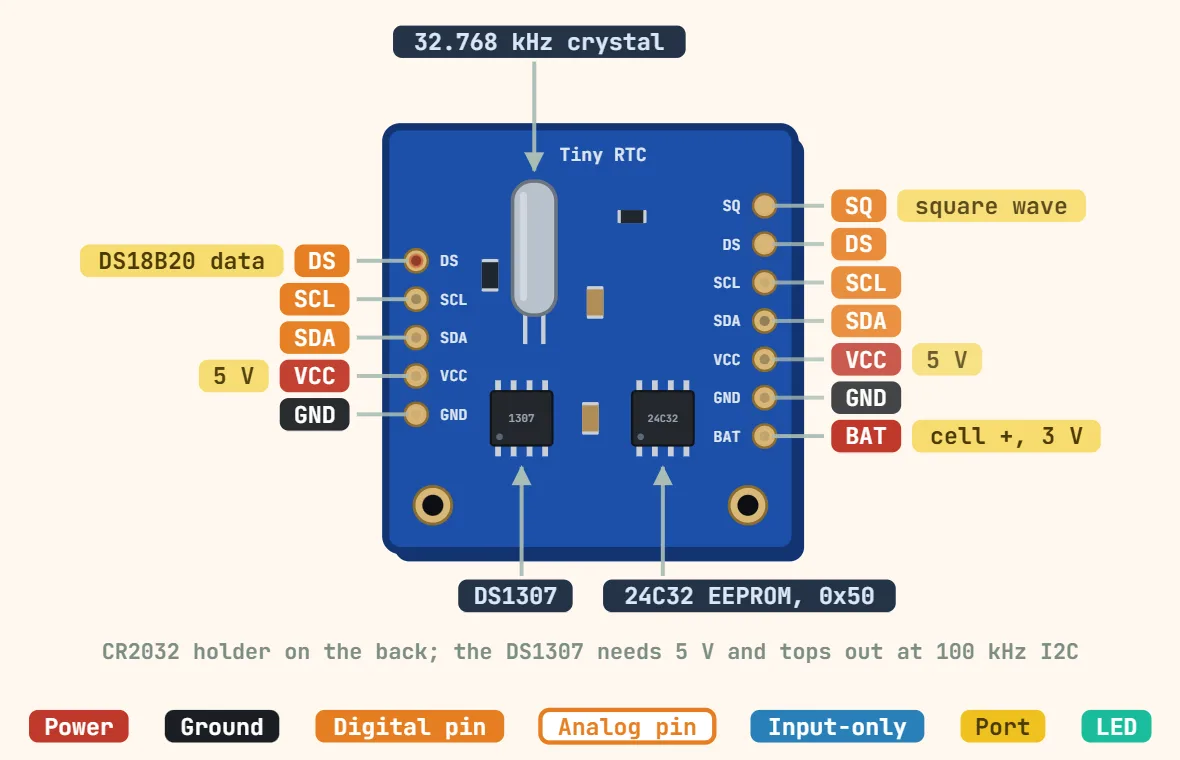 DS1307 RTC moduleSupply voltage: 4.5–5.5 V; Backup battery: 2.0–3.5 V (CR2032 on most modules); Battery current: ≈ 500 nA typ with oscillator running
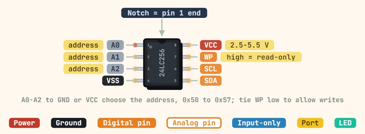 24LC256 I2C EEPROMCapacity: 256 Kbit (32 KB); Supply voltage: 24LC256: 2.5–5.5 V; 24AA256: 1.7–5.5 V; Interface: I2C, 400 kHz (24FC256: 1 MHz)
Transistors, op-amps & analog
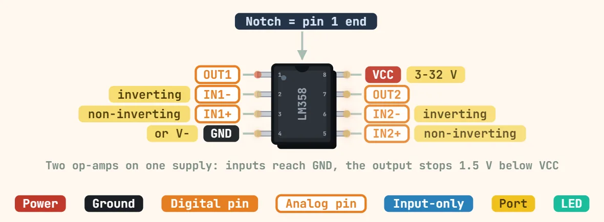 Dual op-amp (DIP-8, e.g. LM358)Example part: LM358 (LM2904 for automotive/wide temperature); Supply voltage: 3–32 V single, or ±1.5–±16 V dual; Supply current: ≈ 0.5–0.7 mA typ for…
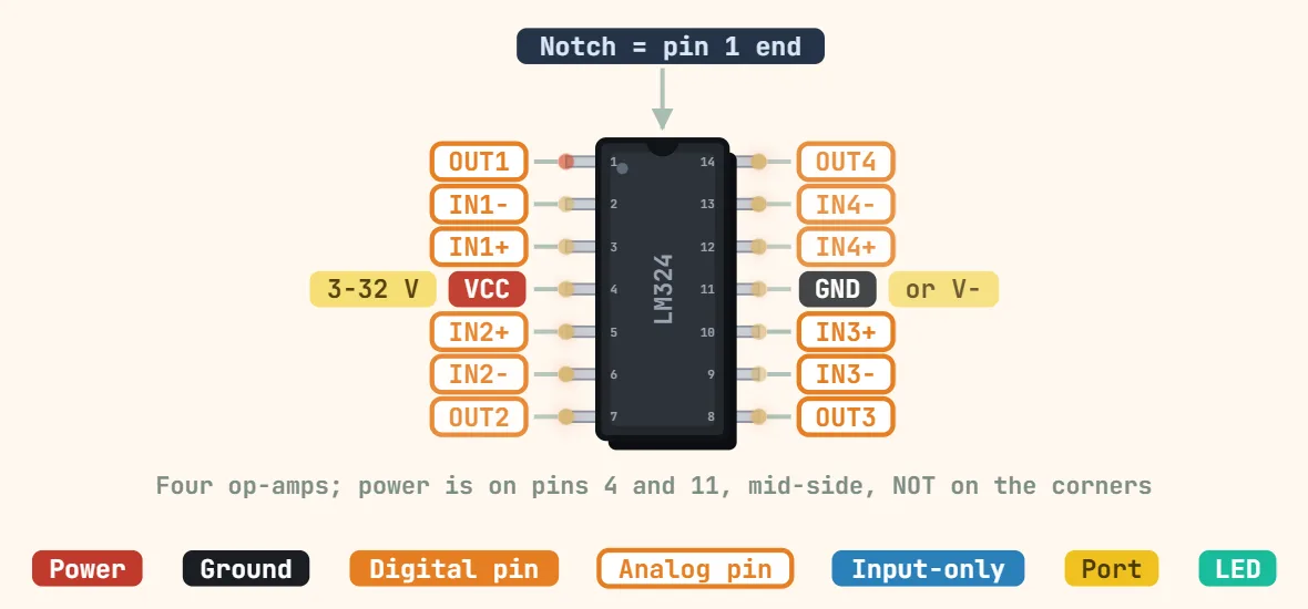 LM324 quad op-amp (DIP-14)Amplifiers: 4 per package, shared supply pins; Supply voltage: 3–32 V single, or ±1.5–±16 V dual; Supply current: ≈ 0.7 mA typ for all four amps
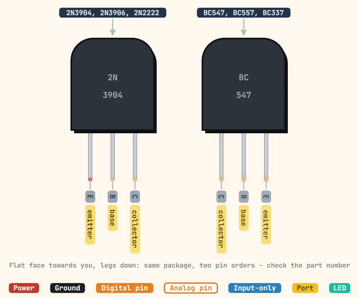 NPN/PNP transistor (TO-92)Example parts: NPN: 2N3904, 2N2222A, BC547; PNP: 2N3906, BC557; Collector–emitter voltage: 2N3904 / 2N2222A: 40 V; BC547: 45 V (PNP versions: −40 / −45…
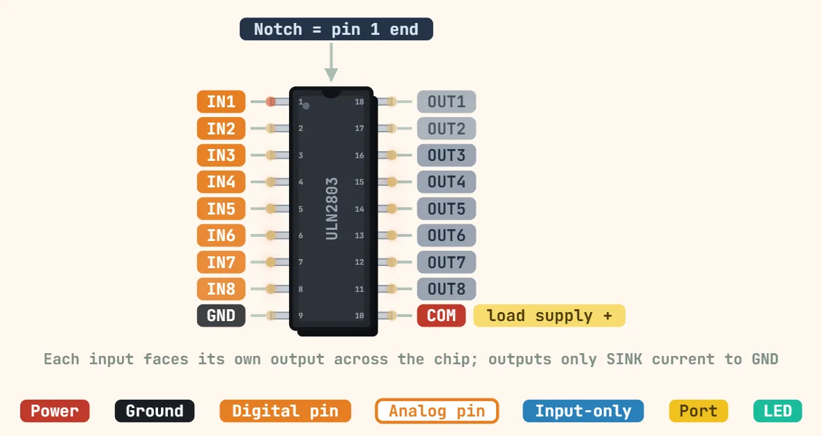 ULN2803 Darlington array (DIP-18)Example part: ULN2803A; Channels: 8 Darlington pairs, open-collector (sinking) outputs; Output voltage: 50 V max
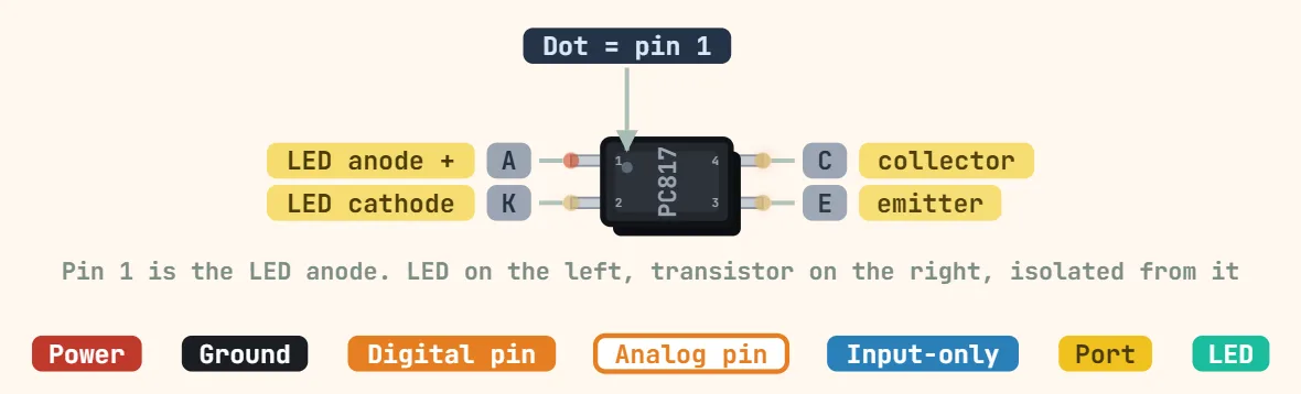 PC817 optocoupler (DIP-4)Isolation voltage: 5000 V rms; LED forward voltage: ≈ 1.2 V typ, 1.4 V max at 20 mA; LED forward current: 50 mA max; typically driven at 5–10 mA
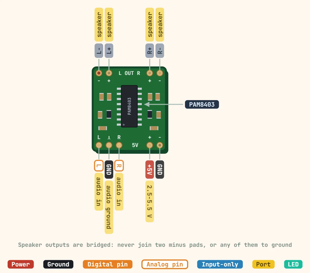 PAM8403 class-D amplifierAmplifier IC: PAM8403 (filterless class-D, stereo); Supply voltage: 2.5–5.5 V; Output power: 3 W per channel into 4 Ω at 5 V (10% THD)
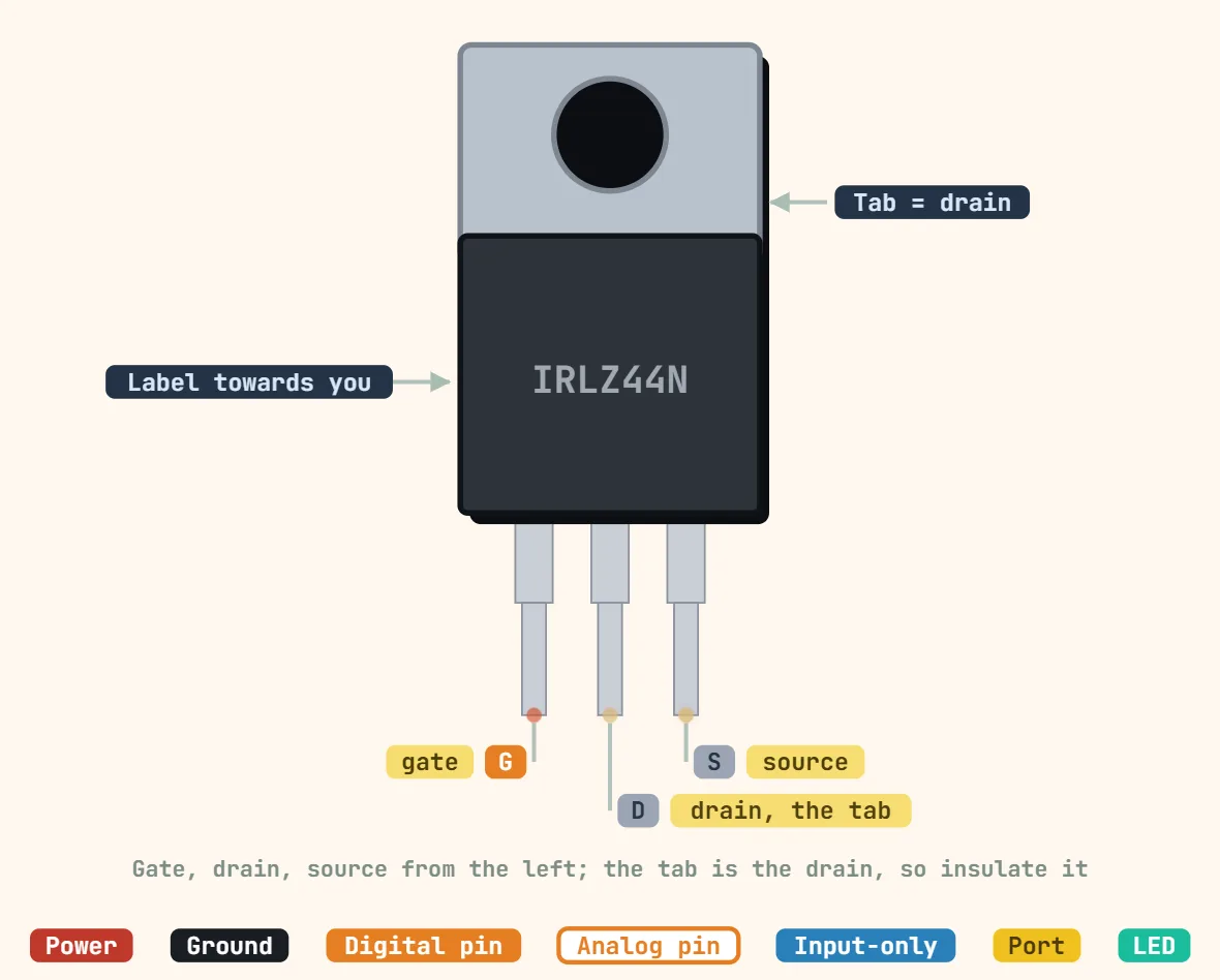 N-channel MOSFET (TO-220, e.g. IRLZ44N)Example part: IRLZ44N (logic-level); Drain–source voltage: 55 V max; Drain current: 47 A max at 25 °C case (limited by heat in practice)
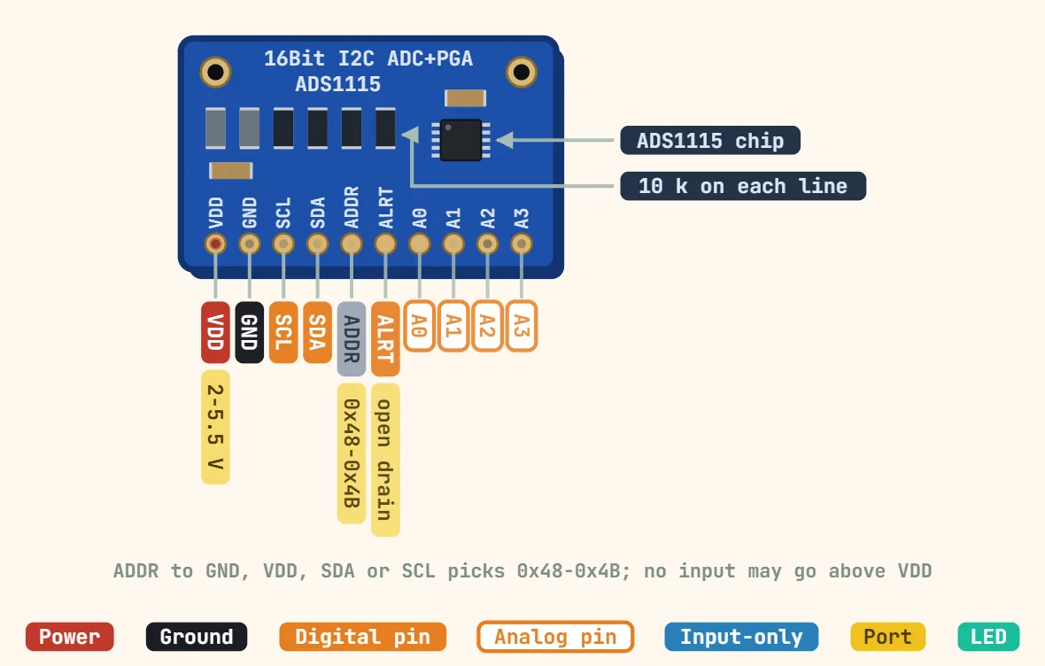 ADS1115 16-bit ADC module (I2C, 10-pin breakout)ADC IC: TI ADS1115; Resolution: 16-bit; Sample rate: 8–860 samples/s, programmable
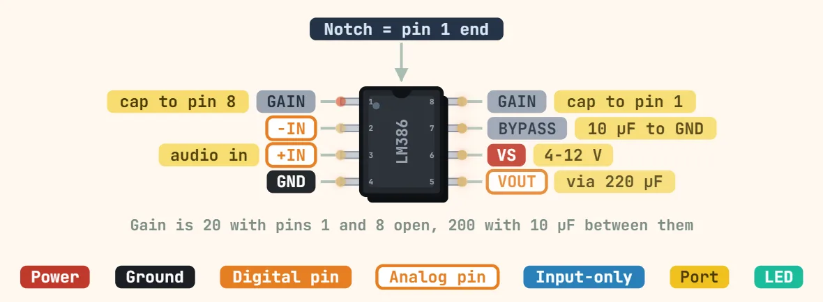 LM386 audio power amplifierSupply voltage: LM386N-1/-3: 4–12 V; LM386N-4: 5–18 V; Quiescent current: ≈ 4 mA typ at 6 V; Output power: N-1: 325 mW (6 V, 8 Ω); N-3: 700 mW (9 V, 8…
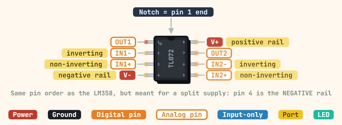 TL072 dual JFET op-ampSupply voltage: TL072: ±5–±15 V recommended, ±18 V absolute max; newer TL072H: 4.5–40 V total; Supply current: ≈ 1.4 mA typ per amplifier;…
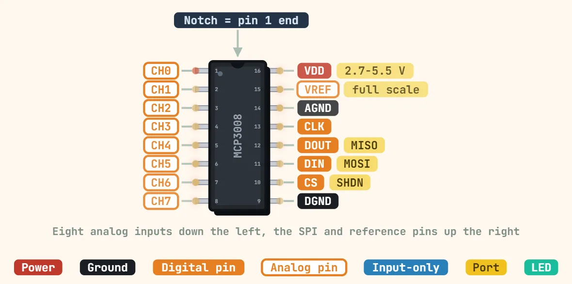 MCP3008 8-channel SPI ADCResolution: 10-bit; Inputs: 8 single-ended or 4 pseudo-differential pairs; Supply voltage: 2.7–5.5 V
Power ICs & modules
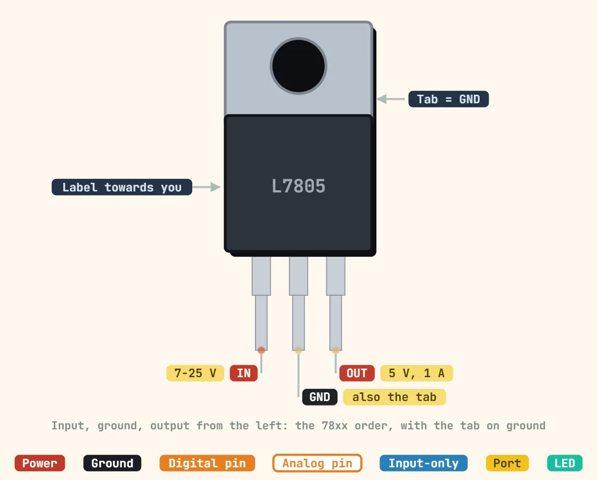 Linear voltage regulator (TO-220, e.g. 7805)Output voltage: 5 V ±4% (7805); 78xx family also 6, 8, 9, 12, 15, 18, 24 V; Input voltage: ≈ 7–25 V in use; 35 V absolute max (5–18 V versions); Dropout:…
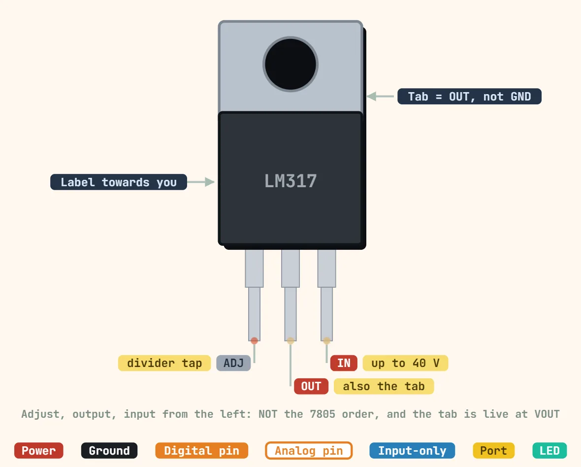 LM317 adjustable regulator (TO-220)Output voltage: 1.25–37 V, set by two resistors; Output formula: Vout = 1.25 V × (1 + R2/R1); R1 typically 240 Ω; Input–output differential: 3–40 V…
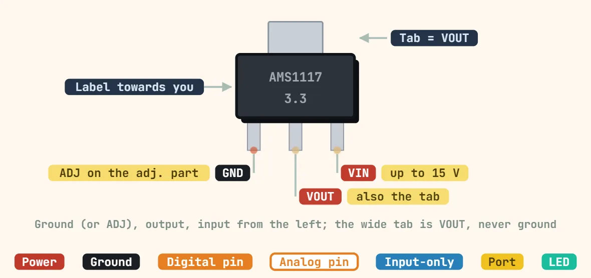 AMS1117 linear regulator (SOT-223)Output voltage: Fixed 1.5, 1.8, 2.5, 2.85, 3.3 or 5.0 V, or adjustable (1.25 V reference); Output current: 1 A; Dropout: ≈ 1.1 V typ, 1.3 V max at 1 A
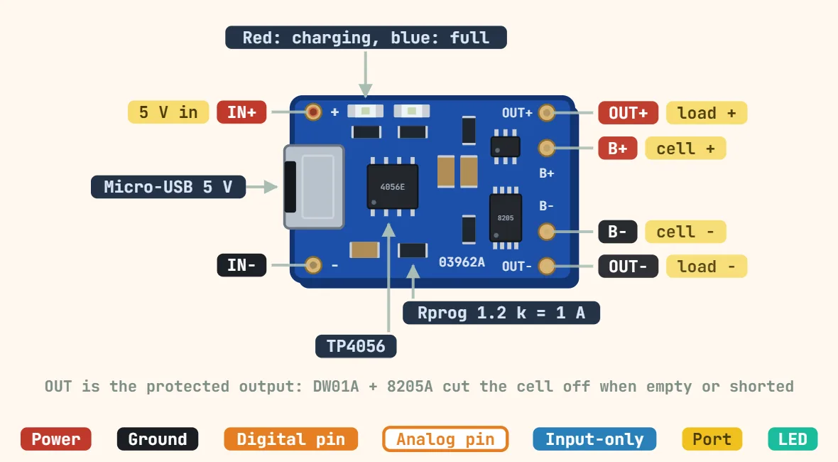 TP4056 Li-ion charger moduleCharger IC: TP4056 (linear, constant current / constant voltage); Input voltage: 5 V nominal (4–8 V per the datasheet); Charge voltage: 4.2 V ±1%
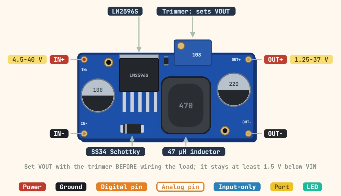 LM2596 buck converter moduleConverter IC: LM2596 (step-down switching regulator); Input voltage: 4.5–40 V; Output voltage: 1.23–37 V adjustable (needs ≈ 1.5 V or more of headroom)