Pinout
MAX485 RS-485 transceiver module (8-pin breakout board) pinout
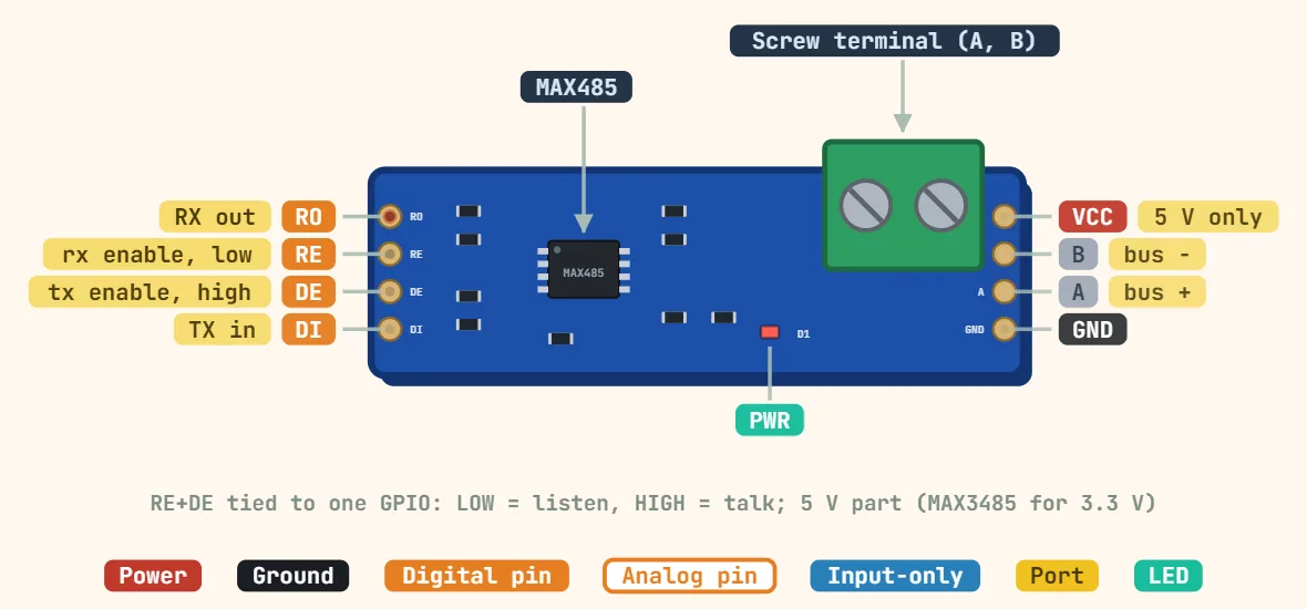
Pins
- RO — receiver output, data coming off the bus (push-pull at VCC, so 5V logic — divide it down before feeding a 3.3V MCU)
- RE — receiver enable, ACTIVE LOW (LOW = listening; HIGH = receiver muted)
- DE — driver enable, active high (HIGH = transmitting). Tie DE to RE and drive both from one GPIO: LOW = receive, HIGH = transmit
- DI — driver input, the TX line from your MCU (idle HIGH; the module does not echo your own bytes back on RO while DE is high — wait for the last byte to finish shifting out before dropping DE or you truncate the frame)
- VCC — 5V only, 4.75–5.25V. The plain MAX485 is NOT a 3.3V part: for a 3.3V MCU use a MAX3485 / SP3485 board instead of feeding this one 3.3V
- A — non-inverting bus line (also silkscreened Y, D+ or A+). Needs a 120Ω termination resistor to B at each of the two physical ends of the bus only
- B — inverting bus line (also silkscreened Z, D− or B−). Idle line state is A above B; a long idle bus needs fail-safe bias resistors (or a transceiver with built-in fail-safe) or the receiver reads noise as data
- GND — must be common with the MCU, and the two ends of the RS-485 cable need a ground/reference conductor between them: A and B alone are not enough over any real distance
Specifications
| Transceiver | MAX485 |
|---|---|
| Supply voltage | 5 V (4.75–5.25 V) |
| Logic level | 5 V (use MAX3485/SP3485 for 3.3 V) |
| Mode | Half-duplex (DE/RE direction control) |
| Data rate | Up to 2.5 Mbps |
| Bus loads | Up to 32 unit loads |
| Common-mode range | −7 to +12 V |
| Cable length | Up to ≈ 1200 m at low baud rates |
| Termination | 120 Ω across A/B at each end of the bus |