Pinout
UART (TTL, 4 pins) pinout
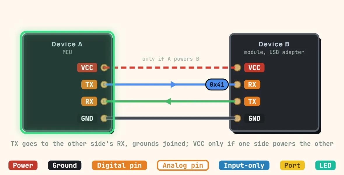
Pins
- VCC
- TX (transmit)
- RX (receive)
- GND
Specifications
| Signals | TX, RX, GND (VCC optional) |
|---|---|
| Topology | Point-to-point, TX crossed to RX |
| Duplex | Full duplex |
| Clock | None (asynchronous), both ends set the same baud rate |
| Common baud rates | 9600, 115200 baud |
| Default frame | 8N1: 1 start, 8 data, no parity, 1 stop bit |
| Logic levels | 0 V / 3.3 V or 5 V, idle high |
| Bit order | LSB first |
| Flow control | Optional RTS / CTS lines |
Notes
- TX of one device goes to RX of the other, and the two grounds must be joined — TX to TX is the classic first mistake. Connect VCC only when one side is powered by the other.
- Both ends must agree on the frame before a single byte is readable: baud rate (within a few percent), data bits, parity and stop bits — 9600 or 115200 baud, 8N1, are the usual defaults. The line idles high; a start bit pulls it low and the data follows, least-significant bit first.
- TTL UART swings between 0 V and the supply (3.3 V or 5 V). A 5 V TX into a 3.3 V-only RX needs a divider or a level shifter. None of this is RS-232, whose ±5–15 V levels are also inverted — that takes a MAX3232-class transceiver.