Pinout
I2S (digital audio bus) pinout
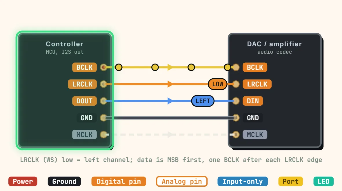
Pins
- BCLK (bit clock)
- LRCLK / WS (word select — left/right channel)
- DIN / DOUT (serial audio data)
- GND
- Some codecs also break out MCLK (master clock)
Specifications
| Signals | BCLK, LRCLK / WS, data in / out (+ optional MCLK) |
|---|---|
| Topology | Point-to-point, controller drives the clocks |
| Clock | Synchronous, BCLK = sample rate × bits × 2 |
| Word select | Low = left, high = right |
| Data format | MSB first, one BCLK after each LRCLK edge (Philips) |
| Typical sample rates | 44.1 kHz, 48 kHz (8–192 kHz) |
| Word length | 16–32 bits |
| MCLK | Usually 256 × sample rate, only for codecs without PLL |
| Addressing / pull-ups | None |
| Range | On-board only |
Notes
- Three signals: the bit clock (BCLK or SCK), the word select (LRCLK or WS — low for the left channel, high for the right) and one data line per direction. The controller normally generates both clocks; a microphone or ADC sends its data back on a separate line, clocked by the same two.
- In the standard (Philips) format the data is MSB first and starts one BCLK period after each LRCLK edge. BCLK runs at the sample rate × the bits per channel × 2: 44.1 kHz × 32 × 2 = 2.8224 MHz is typical.
- MCLK, usually 256 × the sample rate, is only needed by codecs without their own PLL — a MAX98357A or a PCM5102 does without it. Despite the name, I2S has nothing to do with I2C: no addresses and no pull-ups, and a codec that needs configuring has a separate I2C or SPI port for that.