Pinout
I2C (bus) pinout
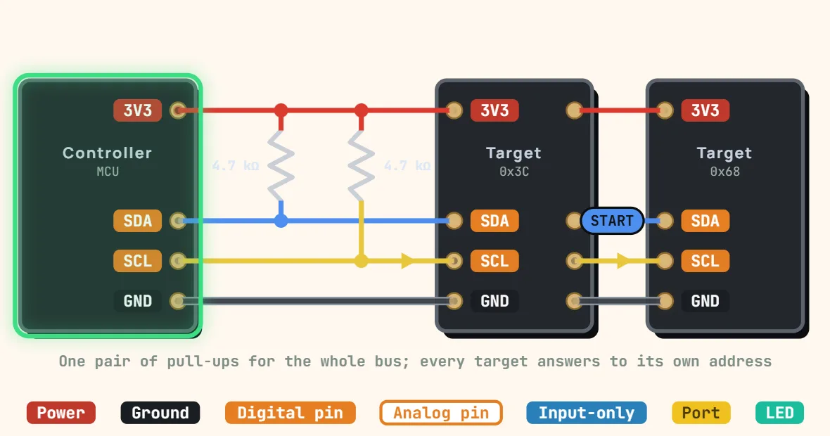
Pins
- VCC
- SDA (data)
- SCL (clock)
- GND
Specifications
| Signals | SDA, SCL + GND |
|---|---|
| Topology | Multi-drop bus, multi-controller capable |
| Duplex | Half duplex |
| Speed | 100 kHz (standard), 400 kHz (fast), 1 MHz (Fast-mode Plus), 3.4 MHz (high speed) |
| Addressing | 7-bit (112 usable addresses), 10-bit optional |
| Output type | Open-drain, one pull-up per line for the whole bus |
| Typical pull-ups | 4.7 kΩ at 100 kHz, 2.2 kΩ at 400 kHz |
| Logic high | Set by the pull-up supply (3.3 V or 5 V) |
| Max bus capacitance | 400 pF (550 pF in Fast-mode Plus) |
Notes
- SDA and SCL are open-drain: devices only ever pull them low, and one pull-up resistor per line returns them high. Fit ONE pair for the whole bus — 4.7 kΩ is the usual start at 100 kHz, 2.2 kΩ at 400 kHz or on longer wiring. Many breakout boards already carry their own pair; several of them in parallel can add up to a pull-up that is too strong.
- Every target answers to a 7-bit address (written 0x3C, 0x68…). Two parts with the same fixed address cannot share a bus without an address-select pin or a multiplexer such as the TCA9548A.
- The pull-ups set the logic-high level. On a mixed-voltage bus, pull up to 3.3 V only if every 5 V device accepts that as a high (check its VIH); otherwise use a level shifter.
- Standard mode is 100 kHz, fast mode 400 kHz. Total bus capacitance is limited to about 400 pF, which is why I2C stays on a board or on short cables.