Pinout
AVR ISP (2×3, 6 pins) pinout
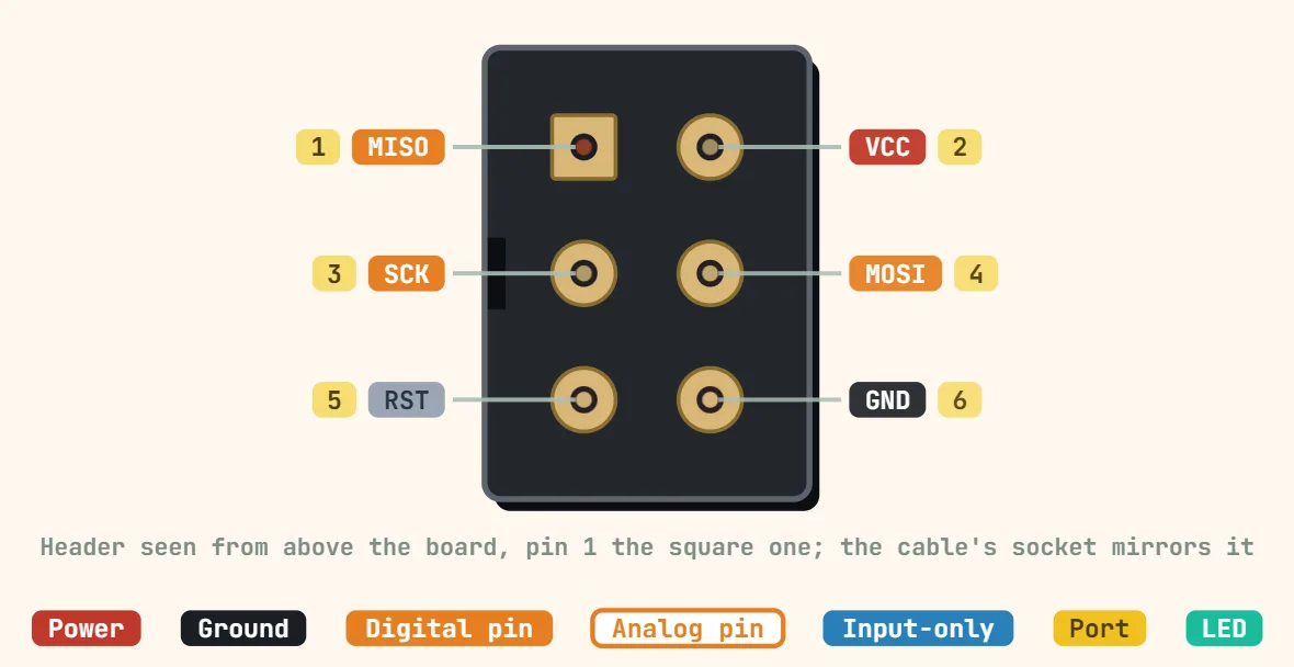
Pins
- 1: MISO
- 2: VCC
- 3: SCK
- 4: MOSI
- 5: RESET
- 6: GND
Specifications
| Contacts | 6 (2 × 3) |
|---|---|
| Pitch | 2.54 mm |
| Signals | MISO, MOSI, SCK, RESET, VCC, GND |
| Protocol | SPI serial programming, RESET held low |
| ISP clock | Below f_CPU / 4 (f_CPU < 12 MHz), f_CPU / 6 (≥ 12 MHz) |
| Voltage | Target's own VCC (sensed by the programmer) |
| Pin 1 | MISO, marked corner |
| Older variant | 10-pin (2 × 5) header, same signals |
| Typical programmers | USBasp, AVRISP mkII, Arduino as ISP |
Notes
- Pin 1 (MISO) is the marked corner — a dot, a 1 or a square pad on the board — and the numbering runs across the two rows: 1-2, 3-4, 5-6. The drawing is the header seen from above the board; the programmer cable's socket, seen from its holes, is the mirror image.
- VCC is normally the TARGET's own supply, which the programmer reads to match its logic levels. Some programmers (a USBasp with its jumper fitted, an Arduino as ISP) can also power the target through it — never from two supplies at once.
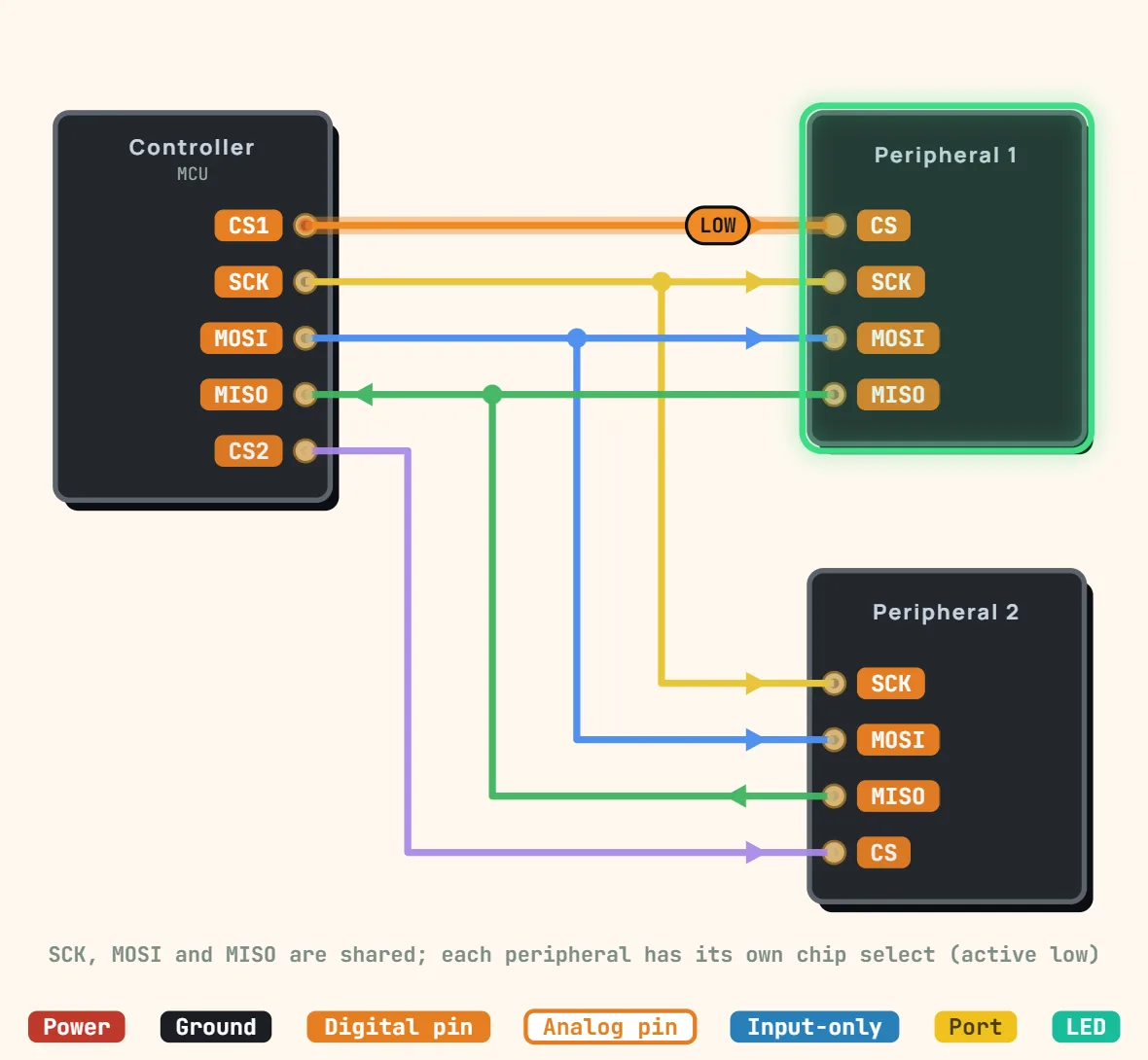
- RESET is held low for the whole programming session, and SCK / MOSI / MISO are the chip's ordinary SPI pins: anything else wired to them that drives or loads the lines can make programming fail.
- The older 10-pin (2×5) layout carries the same six signals: 1 MOSI, 2 VCC, 3 NC, 4 GND, 5 RST, 6 GND, 7 SCK, 8 GND, 9 MISO, 10 GND.