Pinout
CAN bus (2-wire differential) pinout
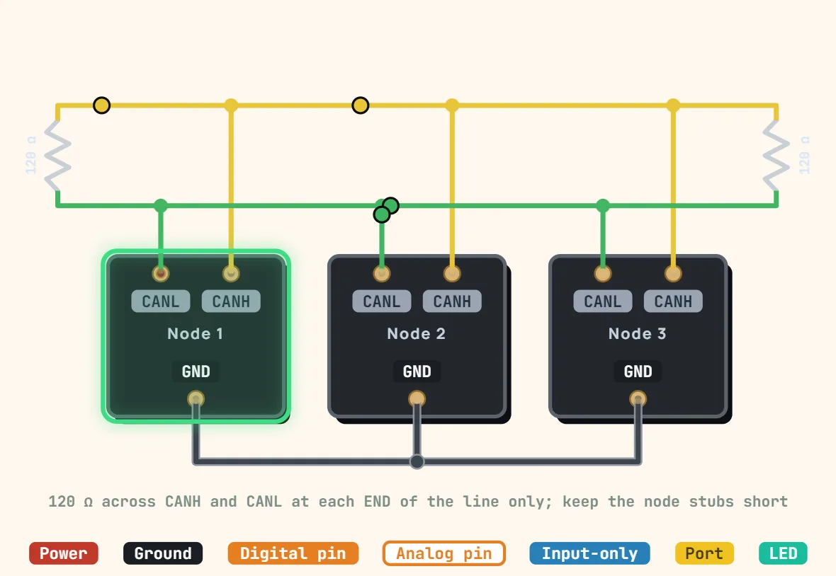
Pins
- CAN_H (dominant high)
- CAN_L (dominant low)
- GND (common reference)
- 120Ω termination resistor at each end of the bus
Specifications
| Signals | CAN_H, CAN_L + common GND |
|---|---|
| Topology | Linear multi-drop bus, multi-master with arbitration |
| Duplex | Half duplex |
| Speed | Up to 1 Mbit/s (classic CAN); 500 kbit/s typical in cars |
| CAN FD | Data phase up to 5–8 Mbit/s |
| Length vs speed | ≈ 40 m at 1 Mbit/s, 100 m at 500 kbit/s, 500 m at 125 kbit/s |
| Termination | 120 Ω at each end (60 Ω total) |
| Levels | Recessive 2.5 V both; dominant CAN_H 3.5 V, CAN_L 1.5 V |
| Identifiers | 11-bit (CAN 2.0A), 29-bit (CAN 2.0B) |
| Transceiver needed | MCP2551, TJA1050, SN65HVD230 |
Notes
- The bus is ONE line of twisted pair with a 120 Ω resistor across CAN_H and CAN_L at each of its two ends, and nowhere else. With the power off, a meter across the pair should read about 60 Ω: 120 Ω means a terminator is missing, 40 Ω that there is one too many.
- Idle (recessive), both wires sit near 2.5 V; a dominant bit drives CAN_H to about 3.5 V and CAN_L to about 1.5 V. The difference carries the data, but the nodes still need a common ground reference to stay inside their transceivers' common-mode range.
- A microcontroller's CAN pins (CTX / CRX, logic level) are NOT the bus: each node needs a transceiver (MCP2551, TJA1050, SN65HVD230…) between them and CAN_H / CAN_L. Keep each node's stub off the main line short — about 30 cm at most at 1 Mbit/s.