Pinout
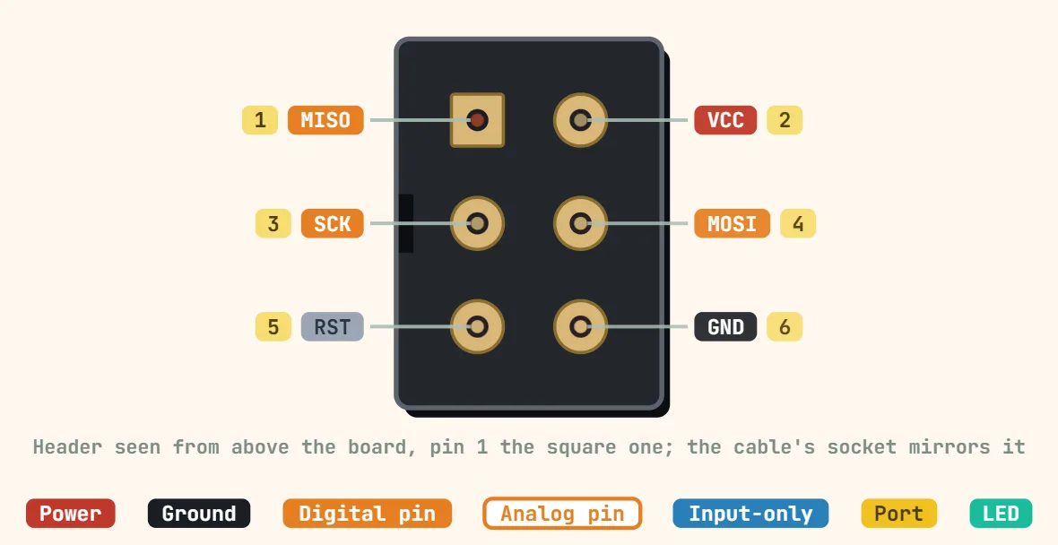
SPI (standard 4-wire) pinout
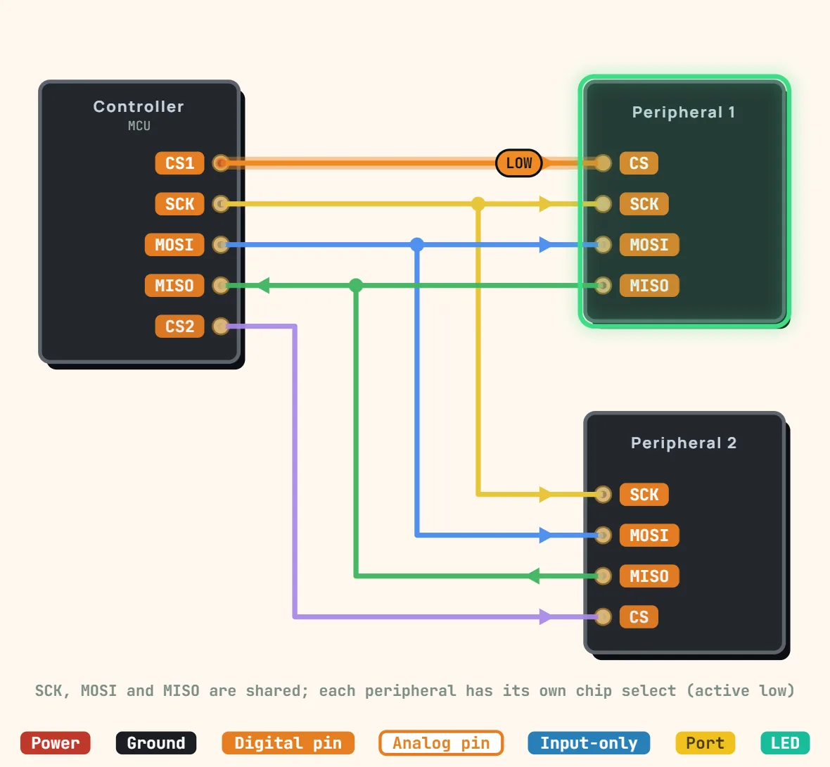
Pins
- MOSI (master → slave)
- MISO (slave → master)
- SCK (clock)
- SS/CS (select)
Specifications
| Signals | SCK, MOSI, MISO, CS (one CS per peripheral) |
|---|---|
| Topology | One controller, several peripherals sharing SCK / MOSI / MISO |
| Duplex | Full duplex, synchronous |
| Clock speed | No standard limit; set by the slowest device and wiring (often 1–50 MHz) |
| Modes | 0–3 (CPOL / CPHA), mode 0 most common |
| Bit order | Usually MSB first |
| Chip select | Active low |
| Addressing | None, chip select picks the device |
| Output type | Push-pull, no pull-ups needed on data lines |
Notes
- SCK, MOSI and MISO are shared by every peripheral; each one has its own chip-select line, active low. A peripheral whose CS is high must release MISO (high impedance) — a module that keeps driving it, as some SD-card and display breakouts do, blocks the bus for the others.
- Newer documents name the data lines by direction: COPI / CIPO (controller out, controller in), or SDO / SDI as printed on each chip, where one device's SDO goes to the other's SDI. They are the same wires as MOSI / MISO.
- Both ends must use the same SPI mode (0 to 3: the clock's idle level, CPOL, and the sampling edge, CPHA) and the same bit order, usually MSB first. Mode 0 is by far the most common; the peripheral's datasheet timing diagram settles it.