Pinout
Raspberry Pi 4 Model B (40-pin GPIO) pinout
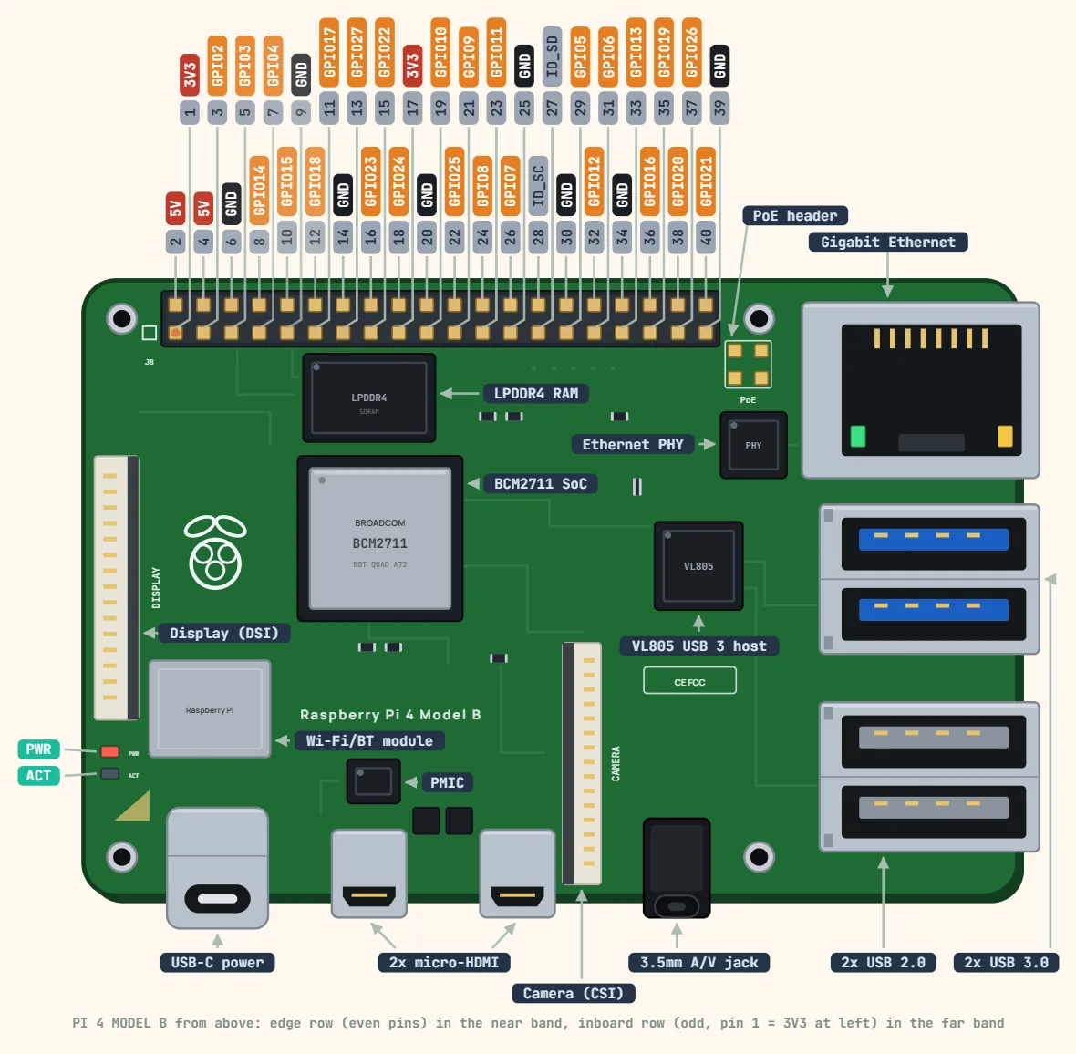
Pins
- 1: 3V3
- 3: GPIO2 — SDA
- 5: GPIO3 — SCL
- 7: GPIO4
- 9: GND
- 11: GPIO17
- 13: GPIO27
- 15: GPIO22
- 17: 3V3
- 19: GPIO10 — COPI
- 21: GPIO9 — CIPO
- 23: GPIO11 — SCLK
- 25: GND
- 27: ID_SD
- 29: GPIO5
- 31: GPIO6
- 33: GPIO13
- 35: GPIO19
- 37: GPIO26
- 39: GND
- 2: 5V
- 4: 5V
- 6: GND
- 8: GPIO14 — TXD
- 10: GPIO15 — RXD
- 12: GPIO18 — PWM
- 14: GND
- 16: GPIO23
- 18: GPIO24
- 20: GND
- 22: GPIO25
- 24: GPIO8 — CE0
- 26: GPIO7 — CE1
- 28: ID_SC
- 30: GND
- 32: GPIO12
- 34: GND
- 36: GPIO16
- 38: GPIO20
- 40: GPIO21
Specifications
| SoC | Broadcom BCM2711, quad-core Cortex-A72 (64-bit) |
|---|---|
| Clock speed | 1.5 GHz (1.8 GHz on later board revisions) |
| RAM | 1, 2, 4 or 8 GB LPDDR4 |
| Power input | 5 V, 3 A via USB-C (or 5 V on GPIO pins) |
| GPIO logic level | 3.3 V (not 5 V tolerant) |
| GPIO current | 16 mA per pin (commonly used budget) |
| GPIO header | 40-pin: 28 GPIO, 2 × 5 V, 2 × 3.3 V, 8 GND |
| Header interfaces | UART, I2C, SPI, PWM, PCM/I2S |
| Wi-Fi | 802.11ac, 2.4 / 5 GHz |
| Bluetooth | 5.0, BLE |
| Ethernet | Gigabit |
| USB | 2 × USB 3.0, 2 × USB 2.0 |
| Video | 2 × micro-HDMI (up to 4Kp60) |
| Size | 85.6 × 56.5 mm |
Notes
- Finding pin 1 on the board: with the header along the top edge and the USB/Ethernet ports to the right, pin 1 (3V3) is the INNER-row pin at the left end of the header, nearest the SD-card end; pin 2 (5V) is the edge-row pin right beside it. Odd pins run along the inboard row, even pins along the board edge.
- The physical pin numbers this list uses (1–40) are not the GPIO/BCM numbers most tutorials and libraries quote — physical pin 3 is GPIO2, physical pin 5 is GPIO3, and so on. Confirm which scheme a wiring guide is using before connecting anything.
- Every pin is 3.3V logic and none are 5V tolerant. Wiring a 5V signal into any GPIO, including a 5V sensor output, can permanently damage that pin.
- GPIO2/GPIO3 (physical 3/5, SDA/SCL) carry fixed 1.8kΩ pull-ups to 3.3V on every standard Pi board, so the primary I2C bus rarely needs external ones — which also makes these two pins a poor choice for plain digital I/O.
- ID_SD/ID_SC (physical 27/28) are a separate, dedicated I2C bus reserved for a HAT’s identification EEPROM. Leave them alone whenever a HAT is fitted.
- This 40-pin layout has been identical across every model with a 40-pin header since the B+ (2014), which is why HATs and pin maps carry over unchanged from that board through the Pi 5.
- A single GPIO is commonly budgeted at 16mA — the Foundation has never published one official number for the COMBINED total across every pin at once, and community measurements for the 3.3V rail range anywhere from roughly 50mA (an old, conservative figure) to 500mA depending on the model’s own regulator. Treat the low end as the safe assumption unless you have measured your specific board.
- The 5V pins are not a separately-regulated rail at all — they are the board’s own incoming 5V supply, straight from the USB-C/micro-USB power input (minus the fuse/polyfuse in the way). Their real ceiling is whatever your power supply and cable can deliver, not a fixed GPIO spec.