Pinout
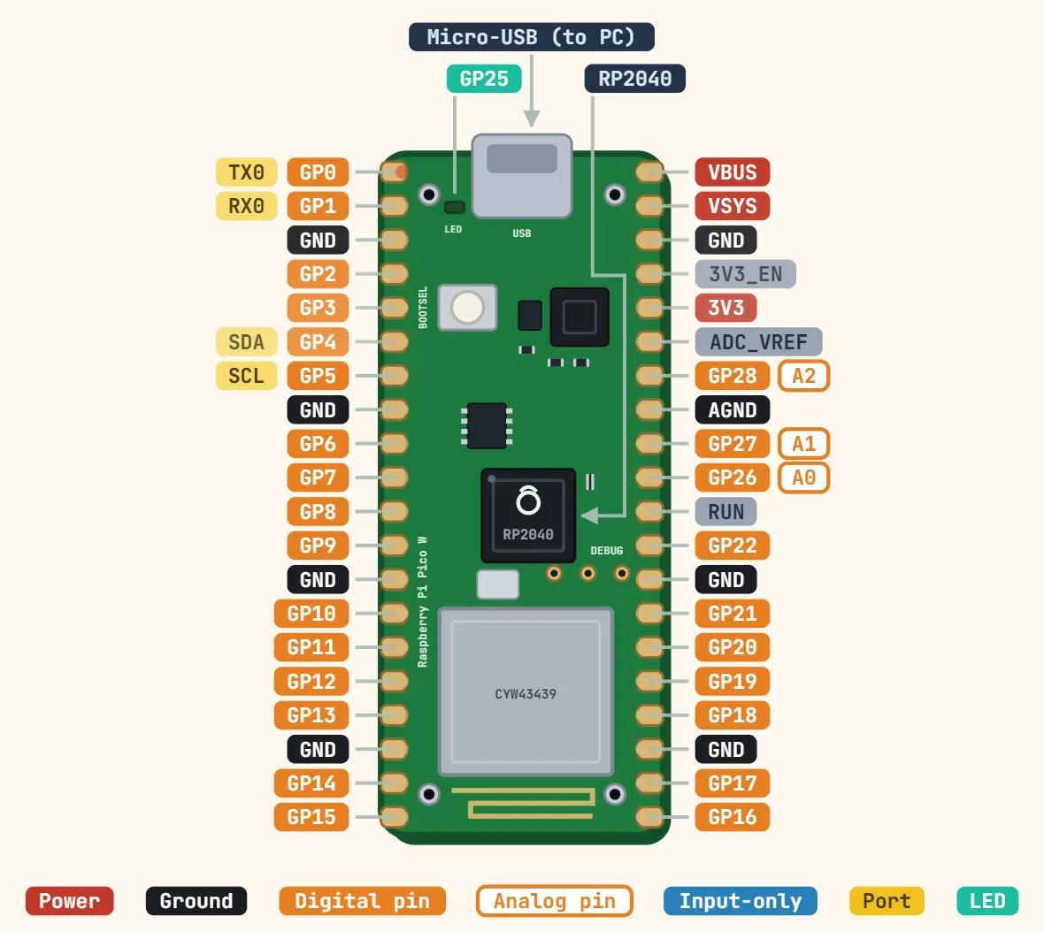
Raspberry Pi Pico (RP2040) pinout
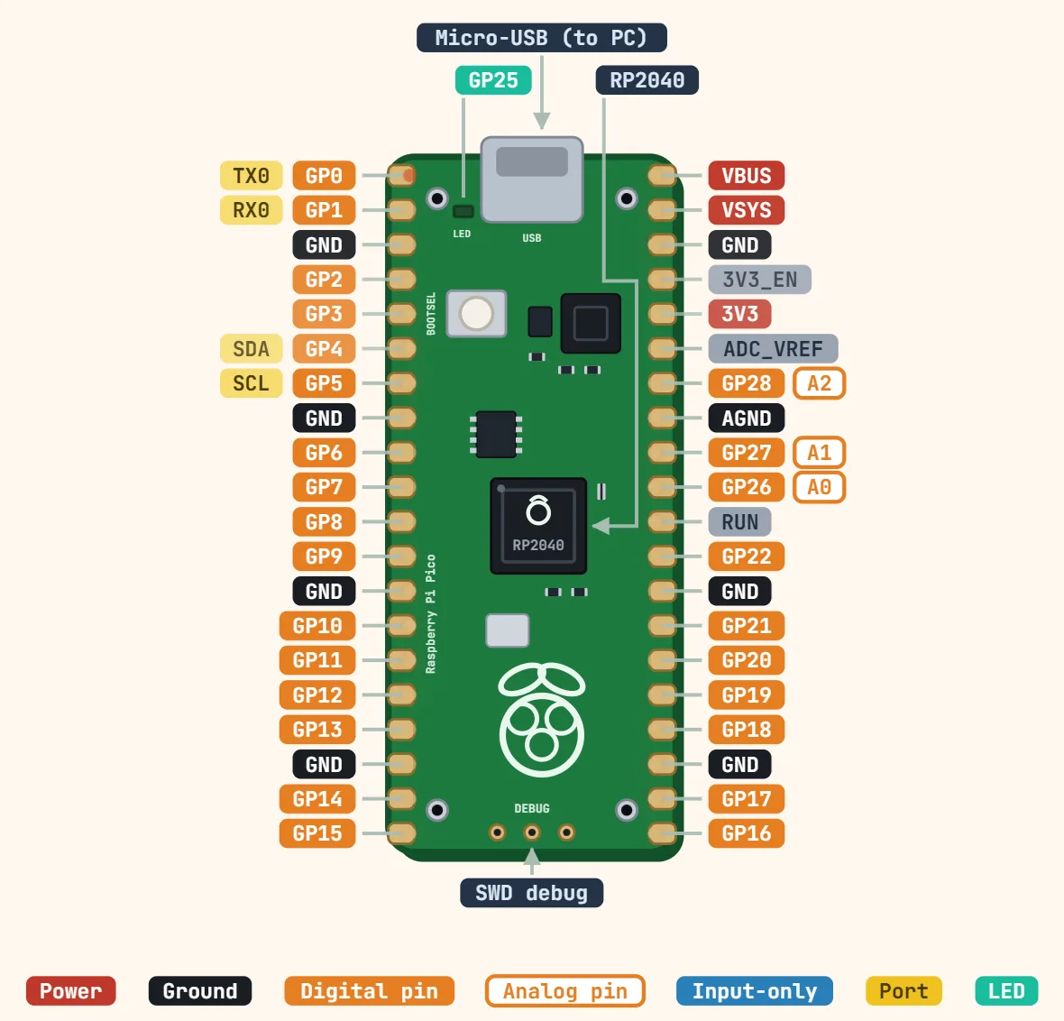
Pins
- 1: GP0 — TX0
- 2: GP1 — RX0
- 3: GND
- 4: GP2
- 5: GP3
- 6: GP4 — SDA
- 7: GP5 — SCL
- 8: GND
- 9: GP6
- 10: GP7
- 11: GP8
- 12: GP9
- 13: GND
- 14: GP10
- 15: GP11
- 16: GP12
- 17: GP13
- 18: GND
- 19: GP14
- 20: GP15
- 40: VBUS
- 39: VSYS
- 38: GND
- 37: 3V3_EN
- 36: 3V3
- 35: ADC_VREF
- 34: GP28 — A2
- 33: AGND
- 32: GP27 — A1
- 31: GP26 — A0
- 30: RUN
- 29: GP22
- 28: GND
- 27: GP21
- 26: GP20
- 25: GP19
- 24: GP18
- 23: GND
- 22: GP17
- 21: GP16
Specifications
| Microcontroller | RP2040, dual-core Arm Cortex-M0+ |
|---|---|
| Clock speed | 133 MHz |
| SRAM | 264 KB |
| Flash memory | 2 MB (external QSPI) |
| Supply (VSYS) | 1.8–5.5 V |
| Logic level | 3.3 V (not 5 V tolerant) |
| GPIO on header | 26 multi-function (GP0–GP22, GP26–GP28) |
| GPIO drive strength | 2, 4, 8 or 12 mA (4 mA default) |
| ADC | 12-bit, 500 ksps, 3 external inputs + temperature sensor |
| Peripherals | 2 × UART, 2 × SPI, 2 × I2C, 16 PWM channels, 8 PIO state machines |
| 3V3(OUT) load | 300 mA max recommended |
| USB | Micro-USB, native USB 1.1 (device/host) |
| Size | 51 × 21 mm |
Notes
- Only GP26, GP27 and GP28 (tagged A0–A2 here) can do analog input — every other GPIO is digital-only, unlike an AVR board where most pins double as both.
- The RP2040’s ADC has a fourth channel too (ADC4), wired to an on-die temperature sensor and readable through the same peripheral without using any external pin.
- GP23, GP24, GP25 and GP29 are real RP2040 GPIOs that this board simply never brings out to a header pin: GP25 drives the onboard LED directly, GP23 sets the regulator’s power-save mode, GP24 senses whether USB power is present, and GP29 (also ADC3) monitors VSYS ÷ 3. Code that "blinks the LED" on a Pico is toggling GP25 with no header pin involved at all.
- Three small pads on the underside carry SWD (GND, SWCLK, SWDIO) for a real hardware debugger — the only way to flash or single-step the board without going through BOOTSEL’s mass-storage drag-and-drop.
- On a Pico W, GP25 is committed to the onboard CYW43439 wireless chip’s own SPI-like bus instead (as its chip-select line) — it does not become a free GPIO. The LED moves onto that same wireless chip’s own driver (`cyw43_arch`/`machine.Pin("LED")`), so code that blinks "the LED" via GP25 on a plain Pico does nothing on a Pico W. See the separate Pico W entry for its own pin-by-pin differences.
- Hold BOOTSEL while plugging in USB and the Pico enumerates as a USB mass-storage drive — drop a .uf2 file on it to flash, no separate programmer or driver needed.
- 3V3_EN pulls the onboard regulator’s enable line low to shut it off entirely; it is there for measuring the board’s own idle current, not something to wire into a normal circuit by accident.
- VSYS accepts unregulated 1.8–5.5V and feeds the onboard 3.3V regulator; VBUS is the raw 5V straight off the USB connector and is only present while a USB cable is plugged in.
- 3V3(OUT) is meant for powering small external circuitry, not just as a logic reference — keep the load on it under ~300mA, the regulator’s own recommended ceiling once the RP2040’s own consumption is accounted for.