Pinout
Raspberry Pi Pico W (RP2040 + CYW43439) pinout
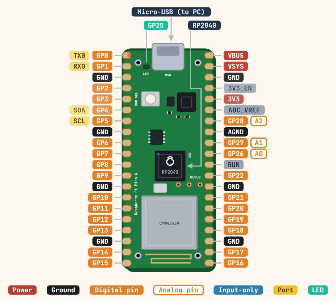
Pins
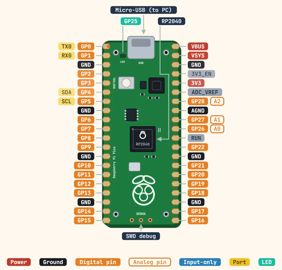
- 1: GP0 — TX0
- 2: GP1 — RX0
- 3: GND
- 4: GP2
- 5: GP3
- 6: GP4 — SDA
- 7: GP5 — SCL
- 8: GND
- 9: GP6
- 10: GP7
- 11: GP8
- 12: GP9
- 13: GND
- 14: GP10
- 15: GP11
- 16: GP12
- 17: GP13
- 18: GND
- 19: GP14
- 20: GP15
- 40: VBUS
- 39: VSYS
- 38: GND
- 37: 3V3_EN
- 36: 3V3
- 35: ADC_VREF
- 34: GP28 — A2
- 33: AGND
- 32: GP27 — A1
- 31: GP26 — A0
- 30: RUN
- 29: GP22
- 28: GND
- 27: GP21
- 26: GP20
- 25: GP19
- 24: GP18
- 23: GND
- 22: GP17
- 21: GP16
Specifications
| Microcontroller | RP2040, dual-core Arm Cortex-M0+ |
|---|---|
| Clock speed | 133 MHz |
| SRAM | 264 KB |
| Flash memory | 2 MB (external QSPI) |
| Wireless chip | Infineon CYW43439 |
| Wi-Fi | 802.11n, 2.4 GHz |
| Bluetooth | 5.2 (Classic + LE) |
| Supply (VSYS) | 1.8–5.5 V |
| Logic level | 3.3 V (not 5 V tolerant) |
| GPIO on header | 26 multi-function (same as Pico) |
| ADC | 12-bit, 500 ksps, 3 external inputs |
| Onboard LED | Driven by the CYW43439 (not GP25) |
| USB | Micro-USB, native USB 1.1 |
| Size | 51 × 21 mm |
Notes
- Same 40-pin header as the plain Pico above — the wireless module changes nothing about the physical pin-out. GP23, GP24, GP25 and GP29 (already internal-only, with no header pin, on the plain Pico too) are now committed to the onboard CYW43439 wireless chip’s own SPI-like bus instead: GP23 = chip enable, GP24 = a shared data/IRQ line, GP25 = chip select, GP29 = clock — still also time-shared with the VSYS ÷ 3 monitor, exactly as on the plain Pico.
- The onboard LED moves with GP25: on the plain Pico that pin drives the LED directly, but on the W it is claimed by the wireless chip-select line instead, so the LED has to be driven through the CYW43439’s own driver (`cyw43_arch` in the Pico SDK, or `machine.Pin("LED")` in MicroPython/CircuitPython). Code copied from a plain-Pico tutorial that blinks GP25/`Pin(25)` directly does nothing on a Pico W — this is the single most common "why won’t my LED blink" report for this board.
- A Wi-Fi join or scan call blocks for real time (up to a few seconds) on first connect — the RP2040 has no OS to schedule around it, so a naive main loop polling a button or a sensor will visibly stall exactly when the radio is busiest. Structure long-running Wi-Fi calls around that, not as an afterthought.
- Same VSYS/VBUS/3V3(OUT) power pins as the plain Pico, with the same ~300mA recommended ceiling on 3V3(OUT) — and now the wireless chip’s own current draw shares that same 3.3V rail, so budgeting external loads against that ceiling matters even more here than on the plain board.