Pinout
SMA connector pinout
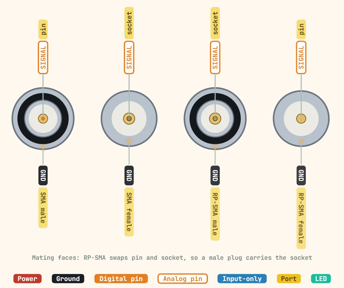
Pins
- Center conductor (signal) — carries the RF signal; the connector's 50Ω characteristic impedance is set by the ratio between this center conductor's diameter and the shell's inner bore, not by any single part on its own.
- Outer shell / coupling body (ground/shield) — the RF return path, not just a mechanical shroud; a loose or cross-threaded coupling raises return loss and shows up as signal loss well before the joint feels mechanically wrong.
- SMA Male (plug) — a free-spinning coupling nut with internal threads that screws onto the mating jack's externally-threaded post, with a pin (protruding center conductor) at its center; this is what's on most antenna pigtail cables.
- SMA Female (jack) — a fixed, externally-threaded post (commonly panel- or PCB-mounted) with a recessed socket at its center to receive the plug's pin; common on bulkhead connectors in radios (e.g. Yaesu/Icom/Kenwood handhelds) and test gear (VNAs, spectrum analyzers) — most consumer WiFi routers use the reverse-polarity version instead (RP-SMA Female, below), not this standard SMA Female.
- RP-SMA Male — the same internally-threaded coupling-nut shell as a standard SMA male plug, but with a SOCKET at its center instead of a pin — the reverse of what "male" means on standard SMA; found on most WiFi/LoRa antenna pigtails.
- RP-SMA Female — the same externally-threaded post shell as a standard SMA female jack, but with a PIN at its center instead of a socket; found on most WiFi/LoRa/cellular bulkhead jacks on dev boards (ESP32, Heltec, TTGO and similar), and on most consumer WiFi routers.
Specifications
| Impedance | 50 Ω |
|---|---|
| Frequency range | DC–18 GHz |
| Thread | 1/4"-36 UNS |
| Coupling torque | 0.8–1.1 N·m (7–10 in·lb), stainless |
| Mating cycles | 500 |
| Variants | SMA and RP-SMA (pin and socket swapped) |
| Typical cable | RG-316, RG-174, semi-rigid |
| Typical use | Wi-Fi / LoRa antennas, radios, RF test gear |
Notes
- RP-SMA and standard SMA thread together identically (a male shell's nut screws onto a female shell's post either way) but are NOT electrically interchangeable: an RP-SMA Male has a socket at its center rather than a pin, so a male-to-male or female-to-female center-contact mismatch between the two families makes no electrical connection even though the parts screw together fine — always check the actual center contact, not just the male/female label, before ordering a pigtail or adapter.
- The reverse-polarity scheme traces back to a widely-cited FCC rule (47 CFR 15.203) for unlicensed consumer transmitters: requiring a non-standard antenna connector discourages swapping in a higher-gain antenna without re-certifying the device. RP-SMA became the de facto connector used to satisfy that rule on consumer WiFi gear, and LoRa modules inherited it from there.
- SMA threads are comparatively fine and fragile next to BNC or N-type — hand-tight plus roughly an eighth to a quarter turn with a wrench is the usual guidance; cranking it down with pliers is a common way to strip the coupling nut or crack the connector's dielectric on a hobbyist antenna pigtail.
- A visually near-identical 75Ω SMA variant exists (mostly older test and video gear) alongside the standard 50Ω used for WiFi, LoRa and general RF work — the two thread together with no mechanical warning, so an impedance mismatch shows up only as degraded return loss/VSWR, never as a fit problem.
- On most ESP32/LoRa dev boards the external RP-SMA bulkhead jack reaches the radio through a short U.FL/IPEX pigtail inside the enclosure, not a direct PCB trace — a poorly seated U.FL connector is a common cause of a dead antenna port that has nothing to do with the SMA connector itself.