Pinout
Ethernet (RJ45, T568B) pinout
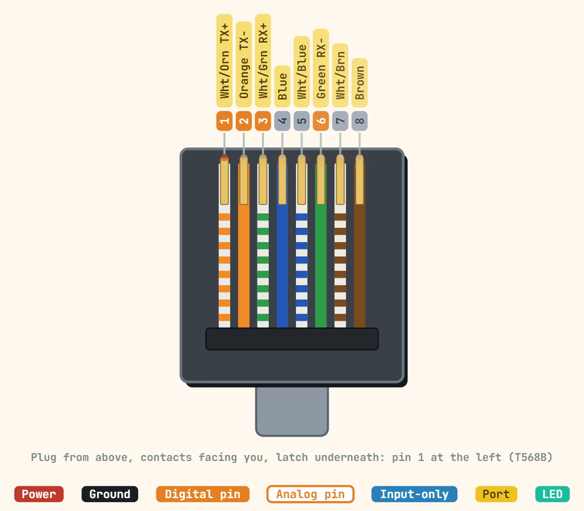
Pins
- 1: White/Orange (TX+)
- 2: Orange (TX−)
- 3: White/Green (RX+)
- 4: Blue
- 5: White/Blue
- 6: Green (RX−)
- 7: White/Brown
- 8: Brown
Specifications
| Contacts | 8 (8P8C) |
|---|---|
| Contact pitch | 1.02 mm |
| Pairs used | 2 pairs (10/100BASE-T, pins 1-2, 3-6), 4 pairs (1000BASE-T) |
| Data rate | 100 Mbit/s (Cat5), 1 Gbit/s (Cat5e), 10 Gbit/s (Cat6a) |
| Max segment length | 100 m |
| Pair impedance | 100 Ω |
| PoE power at source | 15.4 W (802.3af), 30 W (802.3at), 60 / 90 W (802.3bt) |
| Mating cycles | 750 (IEC 60603-7) |
| Wiring | T568A or T568B, same standard at both ends |
Notes
- The drawing is the crimping view: latch underneath, gold contacts facing you, cable toward you — pin 1 is at the left. Looking into a jack with its latch slot at the bottom reads the same 1-8 from left to right; looking at the nose of the plug end-on mirrors it (8 to 1).
- T568A swaps the orange and green pairs relative to T568B above: 1 White/Green (TX+), 2 Green (TX−), 3 White/Orange (RX+), 4 Blue, 5 White/Blue, 6 Orange (RX−), 7 White/Brown, 8 Brown. Either standard works as long as both ends of one cable use the same one — mixing them on a straight-through cable is what makes an accidental crossover cable.
- PoE (802.3af/at) rides on top of the data pairs, not a separate set of wires. Mode A powers over pins 1,2 and 3,6 — the same pairs 10/100BASE-T already uses for data. Mode B powers over pins 4,5 and 7,8, which are spare on 10/100BASE-T but carry data too on Gigabit — PoE still works there because it phantom-powers through the centre tap of each pair’s transformer, underneath whatever signal is riding it.