Pinout
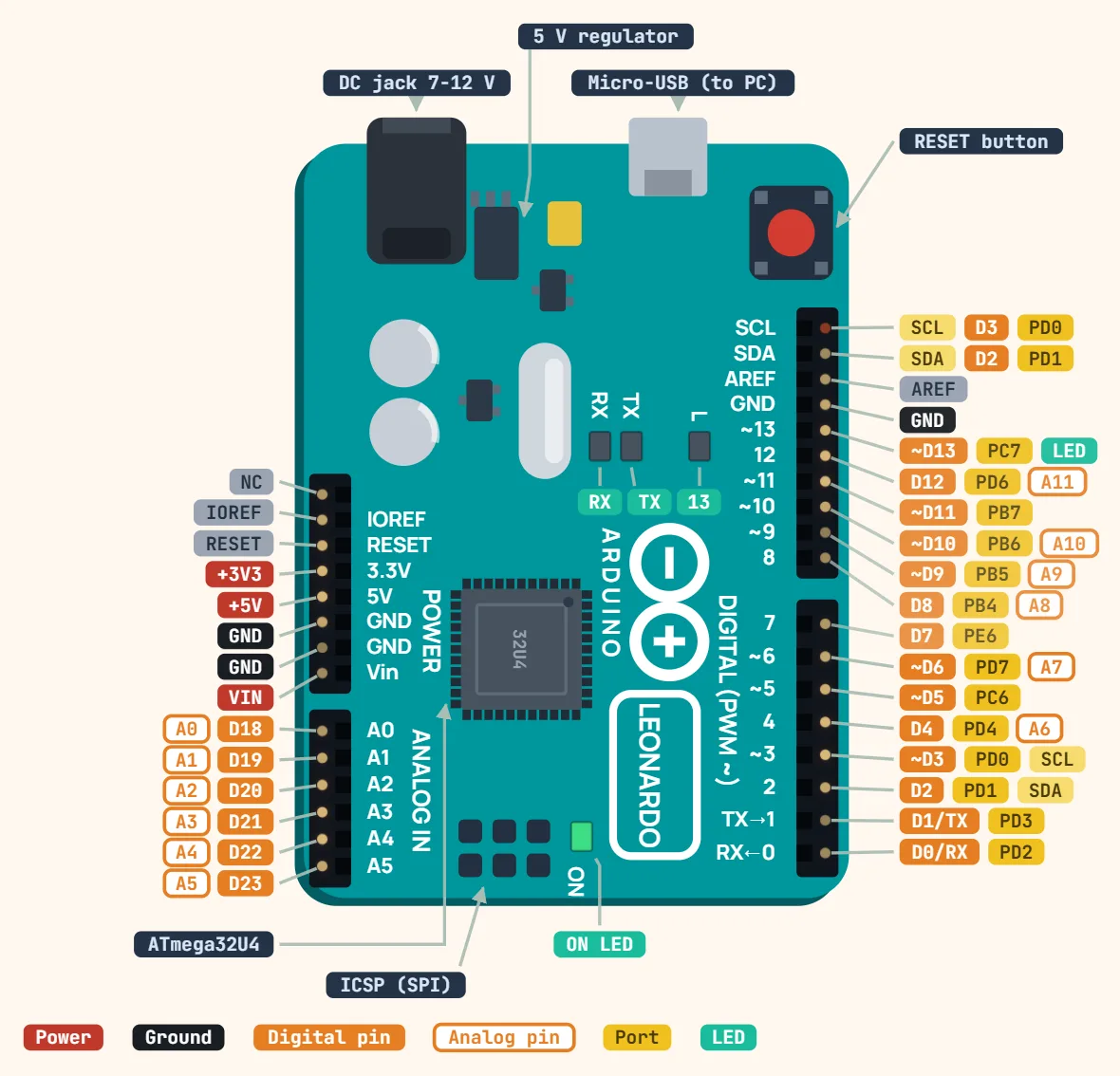
Arduino Uno R3 pinout
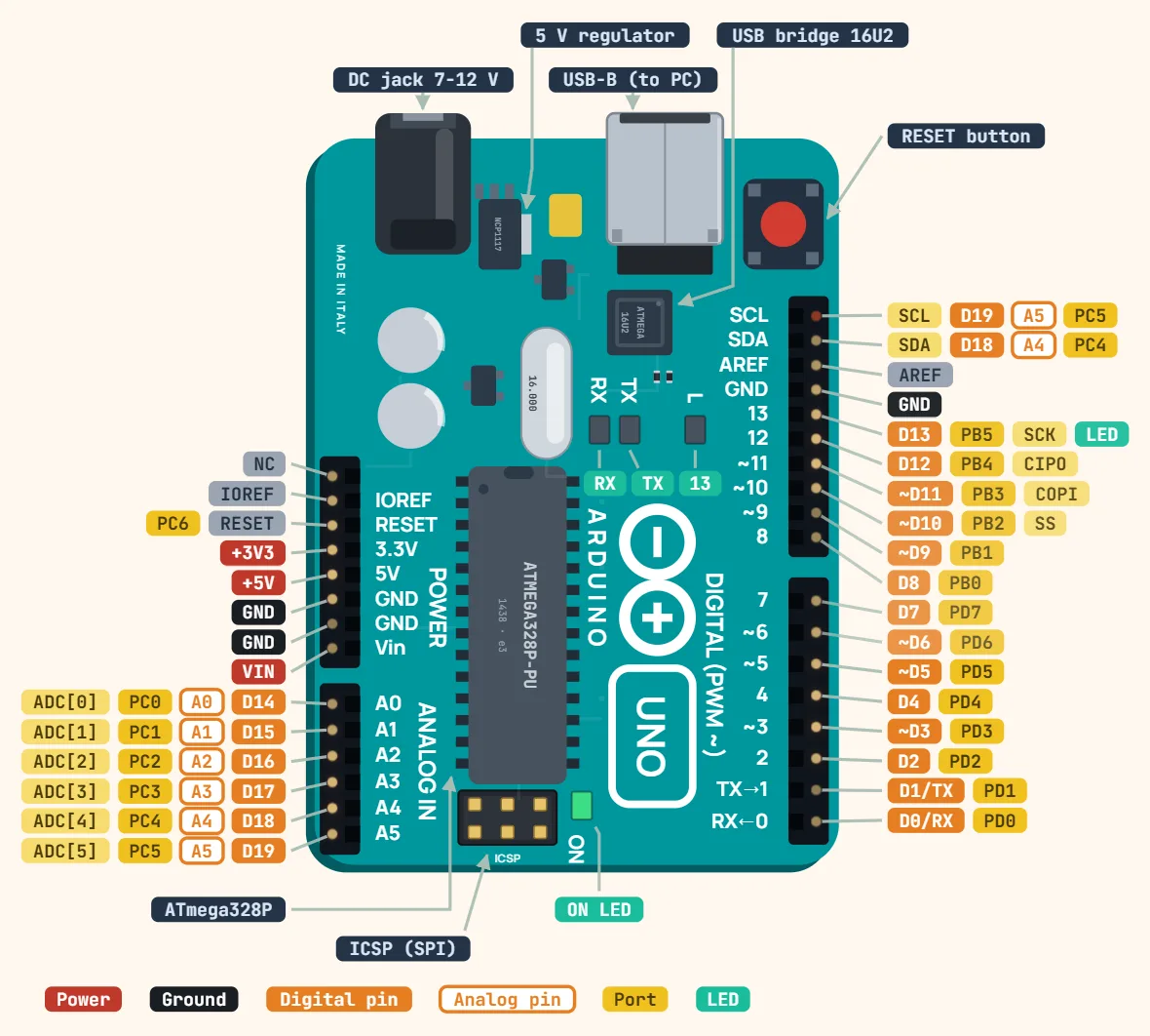
Pins
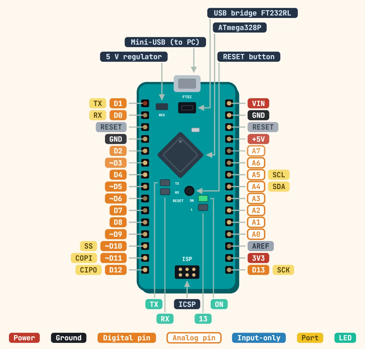
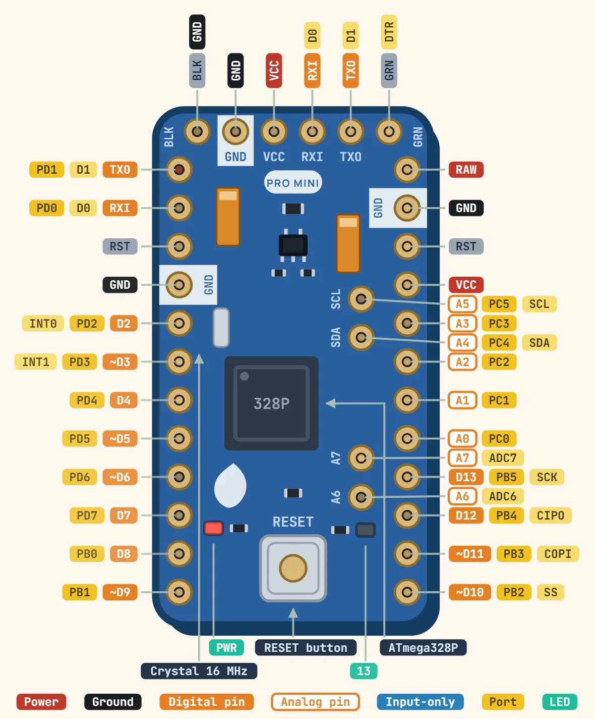
- D0/RX — PD0 (serial in)
- D1/TX — PD1 (serial out)
- D2 — PD2
- ~D3 — PD3 (PWM)
- D4 — PD4
- ~D5 — PD5 (PWM)
- ~D6 — PD6 (PWM)
- D7 — PD7
- D8 — PB0
- ~D9 — PB1 (PWM)
- ~D10 — PB2 (PWM, SPI SS)
- ~D11 — PB3 (PWM, SPI COPI)
- D12 — PB4 (SPI CIPO)
- D13 — PB5 (SPI SCK, LED_BUILTIN)
- AREF — analog reference
- GND — three pins: one by AREF, two on the power header
- A0…A5 — PC0…PC5 (ADC[0…5], usable as D14…D19)
- A4/SDA, A5/SCL — I²C bus (shared)
- SCL, SDA (above AREF) — dedicated I²C header pins, the same two nets as A5/A4
- Power header: NC, IOREF, RESET (PC6), +3V3, +5V, GND, GND, VIN
Specifications
| Microcontroller | ATmega328P |
|---|---|
| Operating voltage | 5 V |
| Input voltage (recommended) | 7–12 V |
| Input voltage (limit) | 6–20 V |
| Digital I/O pins | 14 (6 PWM) |
| Analog input pins | 6 |
| DC current per I/O pin | 20 mA (40 mA absolute max) |
| DC current for 3.3 V pin | 50 mA |
| Flash memory | 32 KB, of which 0.5 KB used by bootloader |
| SRAM | 2 KB |
| EEPROM | 1 KB |
| Clock speed | 16 MHz |
| USB | Type-B, ATmega16U2 USB-serial |
| Size | 68.6 × 53.4 mm |
Notes
- 40mA absolute maximum per I/O pin, 200mA total across all of VCC/GND combined — the ATmega328P's own datasheet limit. Several LEDs or a small relay coil, none individually close to 40mA, can still add up past the 200mA total.
- The 3.3V pin is officially specified at 50mA max, fed from its own small onboard regulator rather than the 5V rail — fine for a sensor breakout, not for a motor or an LED strip.