Pinout
SparkFun Pro Micro (ATmega32U4) pinout
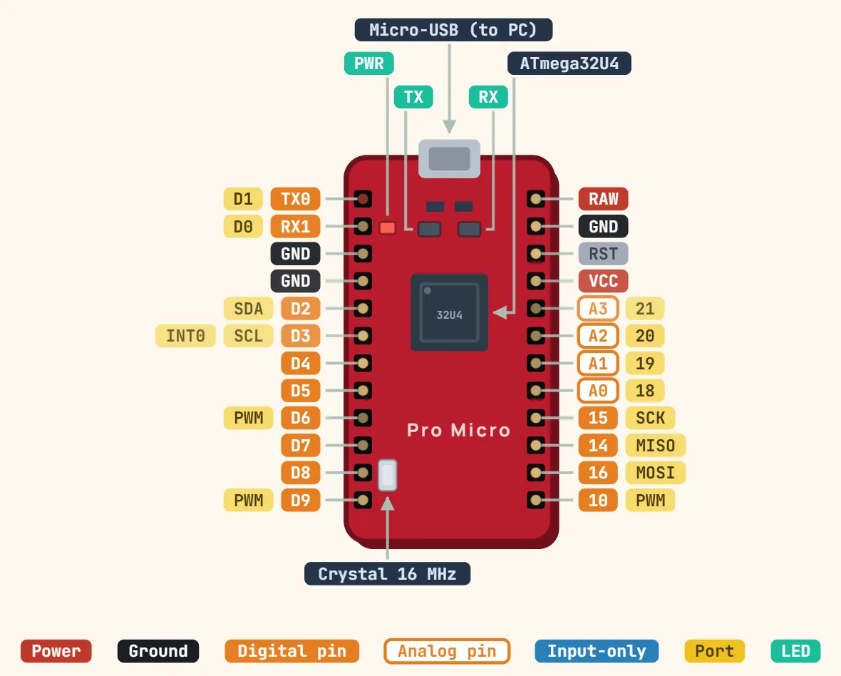
Pins
- TX0 — D1
- RX1 — D0
- GND
- GND
- D2 — SDA
- D3 — SCL — INT0
- D4
- D5
- D6 — PWM
- D7
- D8
- D9 — PWM
- RAW
- GND
- RST
- VCC
- A3 — 21
- A2 — 20
- A1 — 19
- A0 — 18
- 15 — SCK
- 14 — MISO
- 16 — MOSI
- 10 — PWM
Specifications
| Microcontroller | ATmega32U4 |
|---|---|
| Versions | 5 V / 16 MHz or 3.3 V / 8 MHz |
| Input voltage (RAW) | up to 12 V (5 V version needs ≥ 6 V on RAW) |
| I/O pins | 18, of which 9 analog-capable |
| PWM pins | 5 (3, 5, 6, 9, 10) |
| DC current per I/O pin | 20 mA (40 mA absolute max) |
| Flash memory | 32 KB, of which 4 KB used by bootloader |
| SRAM | 2.5 KB |
| EEPROM | 1 KB |
| USB | Micro-B, native (keyboard / mouse capable) |
| Size | 33 × 18 mm |
Notes
- Native USB: the ATmega32U4 has its own built-in USB controller and enumerates directly, unlike the Uno/Nano, which rely on a separate USB-to-serial chip (FTDI/CH340/16U2) — there is no such chip here to reset if an upload stalls. Double-tap RST (or briefly short it to GND twice) to force the bootloader instead.
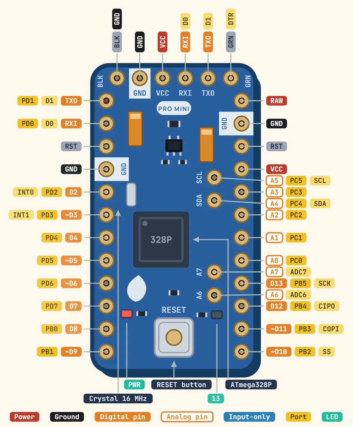
- Two variants share this exact 24-pin layout: a 5V/16MHz board and a 3.3V/8MHz board (3.3V silicon is only rated to 8MHz, hence the slower crystal). VCC follows whichever regulator is actually fitted — never feed 5V logic into the I/O pins of the 3.3V variant.
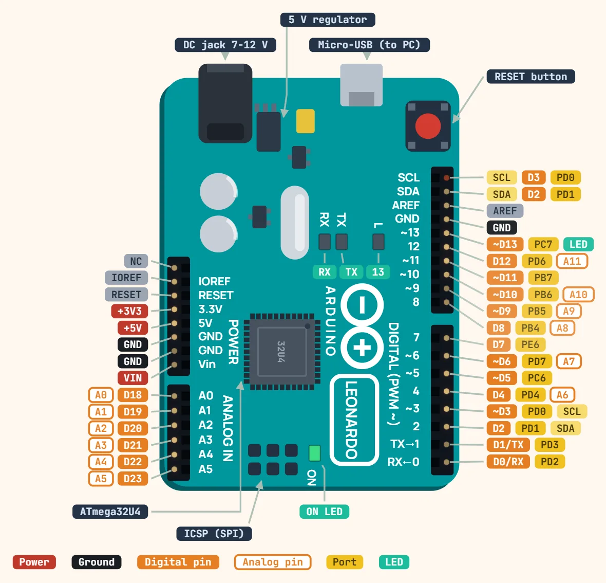
- A6–A9 are analog-only inputs sharing the same physical pins as D4/D6/D8/D9 — they have no pin of their own on the header.
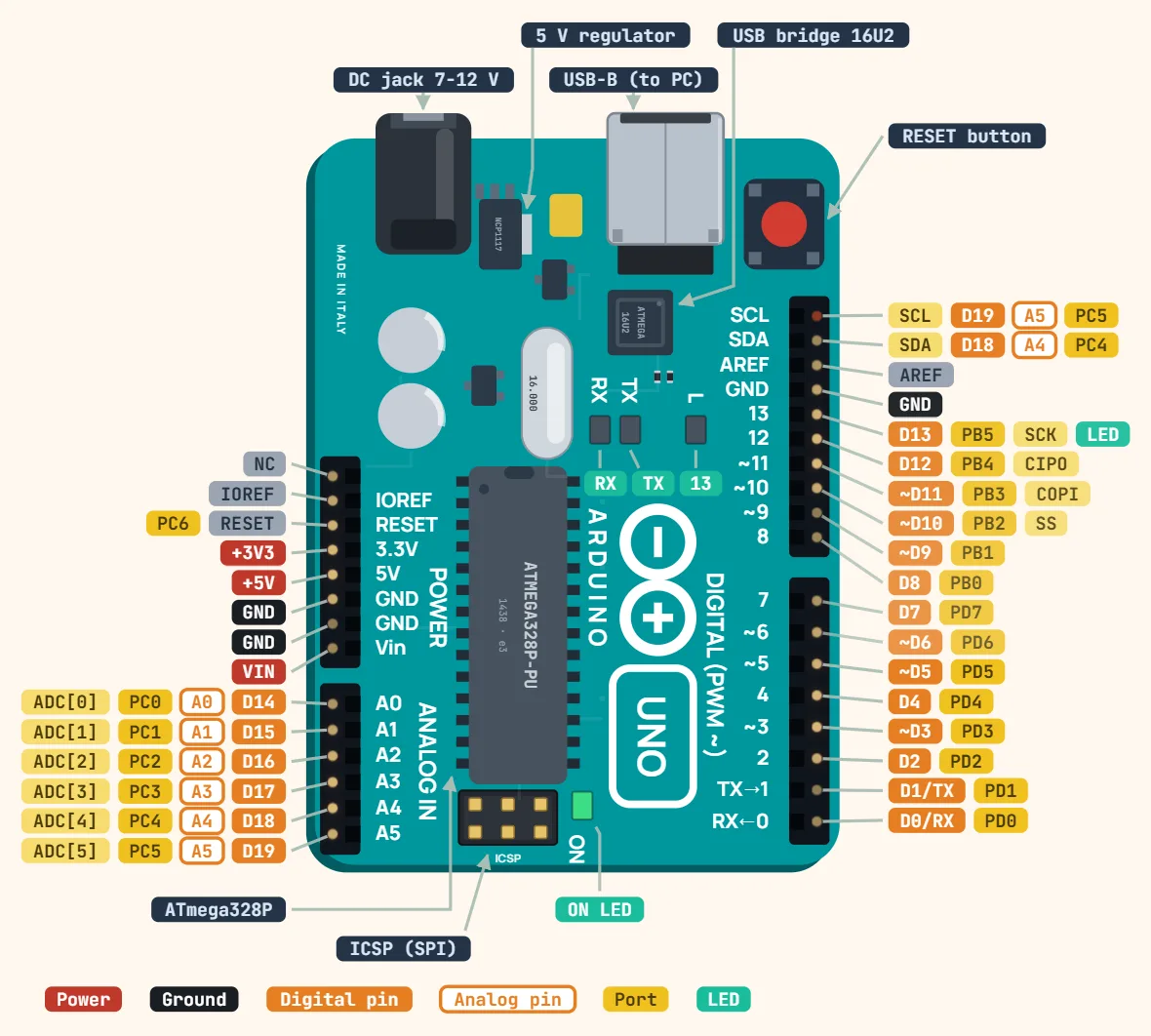
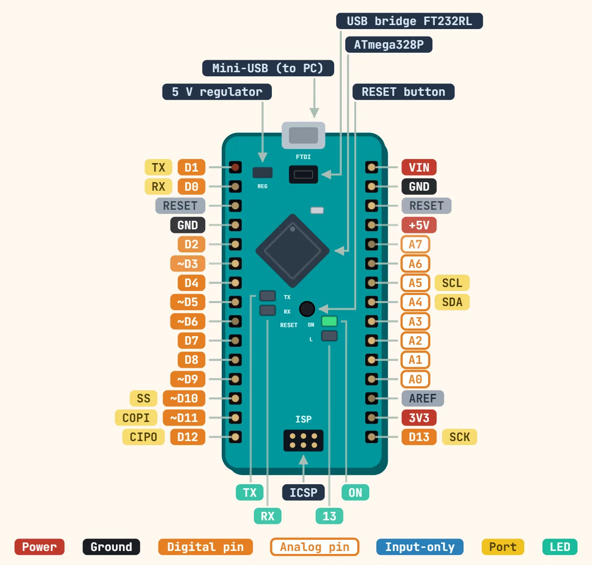
- Same AVR family current limits as the ATmega328P boards above: 40mA absolute maximum per I/O pin, 200mA total through VCC/GND — the native USB controller doesn’t change the power budget, only the enumeration path.