Pinout
Arduino Leonardo pinout
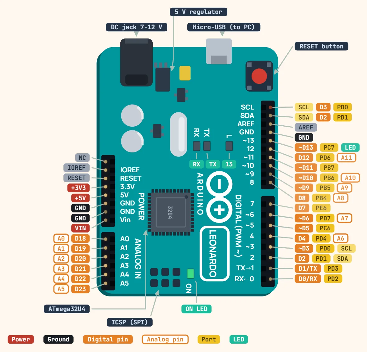
Pins
- D0/RX — PD2, Serial1 hardware UART receive; separate from the USB virtual serial port, also the chip's INT2 line
- D1/TX — PD3, Serial1 hardware UART transmit, also INT3
- D2 — PD1, SDA (I²C data), also INT1
- ~D3 — PD0, SCL (I²C clock), PWM, also INT0
- D4 — PD4, doubles as A6 analog input
- ~D5 — PC6 (PWM)
- ~D6 — PD7, doubles as A7 analog input (PWM)
- D7 — PE6, also the chip's INT6 external-interrupt line
- D8 — PB4, doubles as A8 analog input
- ~D9 — PB5, doubles as A9 analog input (PWM)
- ~D10 — PB6, doubles as A10 analog input (PWM)
- ~D11 — PB7 (PWM)
- D12 — PD6, doubles as A11 analog input
- ~D13 — PC7 (PWM, LED_BUILTIN — onboard LED)
- AREF — analog reference voltage
- GND — three pins: one by AREF, two on the power header
- A0…A5 — dedicated analog inputs, usable as digital D18…D23 (not D14…D19 as on the Uno)
- SCL, SDA (above AREF) — duplicate I²C header pins, same nets as D3/D2
- ICSP header (2×3, next to the USB port) — MISO, VCC, SCK, MOSI, RESET, GND: the only place hardware SPI is actually exposed — D10-D13 carry no SPI signal on this board
- Power header: NC, IOREF, RESET, +3V3, +5V, GND, GND, VIN
Specifications
| Microcontroller | ATmega32U4 |
|---|---|
| Operating voltage | 5 V |
| Input voltage (recommended) | 7–12 V |
| Input voltage (limit) | 6–20 V |
| Digital I/O pins | 20 (7 PWM) |
| Analog input pins | 12 |
| DC current per I/O pin | 20 mA (40 mA absolute max) |
| DC current for 3.3 V pin | 50 mA |
| Flash memory | 32 KB, of which 4 KB used by bootloader |
| SRAM | 2.5 KB |
| EEPROM | 1 KB |
| Clock speed | 16 MHz |
| USB | Micro-B, native (keyboard / mouse capable) |
| Size | 68.6 × 53.3 mm |
Notes
- Native USB, like the SparkFun Pro Micro: the ATmega32U4 enumerates directly as a USB CDC device, so Serial in code refers to that virtual USB port, not a physical UART — the real hardware UART lives on D0/D1 and must be addressed as Serial1. A sketch ported from an Uno that assumes Serial drives the D0/D1 pins will compile fine and simply send nothing out those pins.
- There is no separate USB-to-serial chip to reset the board for a new upload — the IDE does it by briefly opening the port at 1200 baud, which drops the ATmega32U4 into its Caterina bootloader for roughly 8 seconds before it jumps to the sketch. If a bad sketch hangs or disables USB before that handshake can happen, double-tap the RESET button (or briefly short RESET to GND twice within about half a second) to force the bootloader open for a fresh upload.
- Hardware SPI is not on D10-D13 the way it is on an Uno — those four pins are just ordinary GPIO on the 32U4. The real SPI bus (MISO/SCK/MOSI, plus SS) is broken out only on the 2×3 ICSP header beside the USB port, so an Uno-era shield wired to D10-D13 for its SPI device needs jumper wires to the ICSP header to actually work here.
- Arduino rates this board's I/O pins at 20mA maximum each — that's Arduino's own published limit for the Leonardo, not the ATmega32U4 die's absolute destructive rating of 40mA (a last-resort ceiling, not a safe design target, same distinction as on the Uno). The 3.3V pin is limited to about 50mA from its own small onboard regulator rather than the 5V rail.