Pinout
ESP32-C3 SuperMini pinout
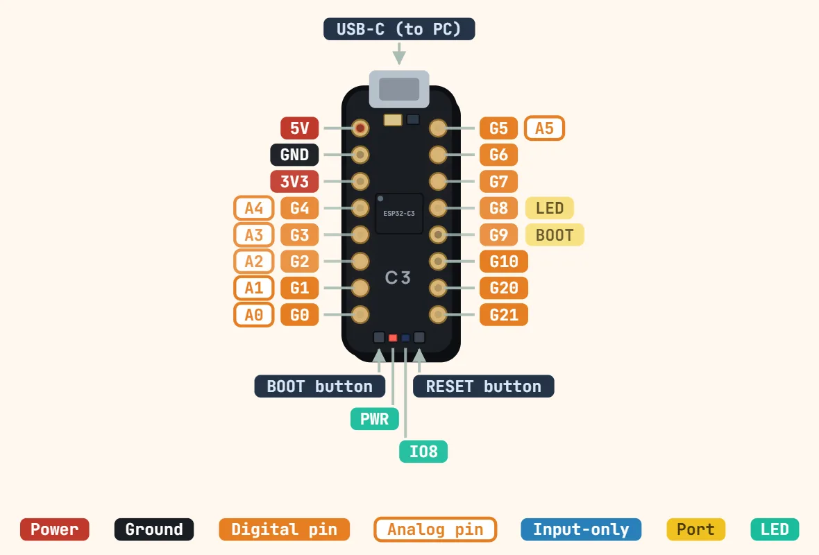
Pins
- 5V
- GND
- 3V3
- G4 — A4
- G3 — A3
- G2 — A2
- G1 — A1
- G0 — A0
- G5 — A5
- G6
- G7
- G8 — LED
- G9 — BOOT
- G10
- G20
- G21
Specifications
| Chip | ESP32-C3, single-core 32-bit RISC-V |
|---|---|
| Clock speed | 160 MHz |
| SRAM | 400 KB |
| Flash memory | 4 MB in-package (typical) |
| Supply | 5 V via USB-C or 5V pin, onboard 3.3 V regulator |
| Logic level | 3.3 V (not 5 V tolerant) |
| GPIO on header | 13 (GPIO0–10, 20, 21) |
| ADC | 12-bit; use ADC1 on GPIO0–4 |
| Wi-Fi | 802.11 b/g/n, 2.4 GHz |
| Bluetooth | 5 (LE only) |
| USB | USB-C, native USB Serial/JTAG |
Notes
- Three boot-mode strapping pins are sampled once at reset: GPIO2 and GPIO8 just need to be free to float or read their default level at power-up, while GPIO9 (wired to the onboard BOOT button) is the one that actually matters day to day — held low at reset it drops the chip into download/flashing mode, the direct equivalent of GPIO0 on a classic ESP32.
- Every GPIO is 3.3V logic only and none are 5V-tolerant — there's no protection like the Mega's, so wiring an old 5V sensor or module (I2C, an HC-SR04, etc.) straight into a pin needs a level shifter or divider first, same as a classic ESP32.
- The chip physically has 22 GPIOs (GPIO0-21), but only 13 are usable on this board: GPIO11-17 are permanently claimed by the in-package SPI flash, and GPIO18/19 are hardwired to the onboard USB-C port's D-/D+ — neither group is ever broken out, which is why the header exposes only GPIO0-10 plus GPIO20/21 as RX/TX.
- USB is native to the chip (a built-in USB Serial/JTAG controller), not a separate USB-to-serial chip — no CH340/CP2102 driver to install, but also usually no automatic DTR/RTS reset circuit, so if a sketch upload doesn't start on its own, hold BOOT, tap RESET, then release BOOT to force download mode by hand.
- The onboard 3.3V regulator is typically only rated for a few hundred mA, while the chip's radio can draw current spikes approaching that during a Wi-Fi transmit burst — a marginal USB cable or port plus that spike is the classic cause of a random reset that looks like a code bug but is really a power problem, the same failure mode seen on other cheap ESP boards.
- There are two ADC units on this chip, mirroring the classic ESP32's ADC1/ADC2 split, just much smaller: ADC1 (12-bit, 5 channels on GPIO0-4, factory-calibrated) and ADC2 (12-bit, 1 channel on GPIO5, uncalibrated). ADC2 is best ignored in practice — it can't be read while Wi-Fi is connected, and Espressif's own chip errata flags a hardware fault in its digital controller — so GPIO0-4 on ADC1 are the only readings worth trusting; averaging a few samples is still the usual way to cut noise while Wi-Fi is active.
- Flash is embedded inside the chip package itself (commonly 4MB on boards sold as 'SuperMini', though some clones ship less) rather than a separate visible chip, so — unlike a WROOM-module board — there's no second chip on the PCB to read a part number off; check the actual size with esptool or the IDE's board info instead of assuming.