Pinout
ESP32-CAM (AI-Thinker) pinout
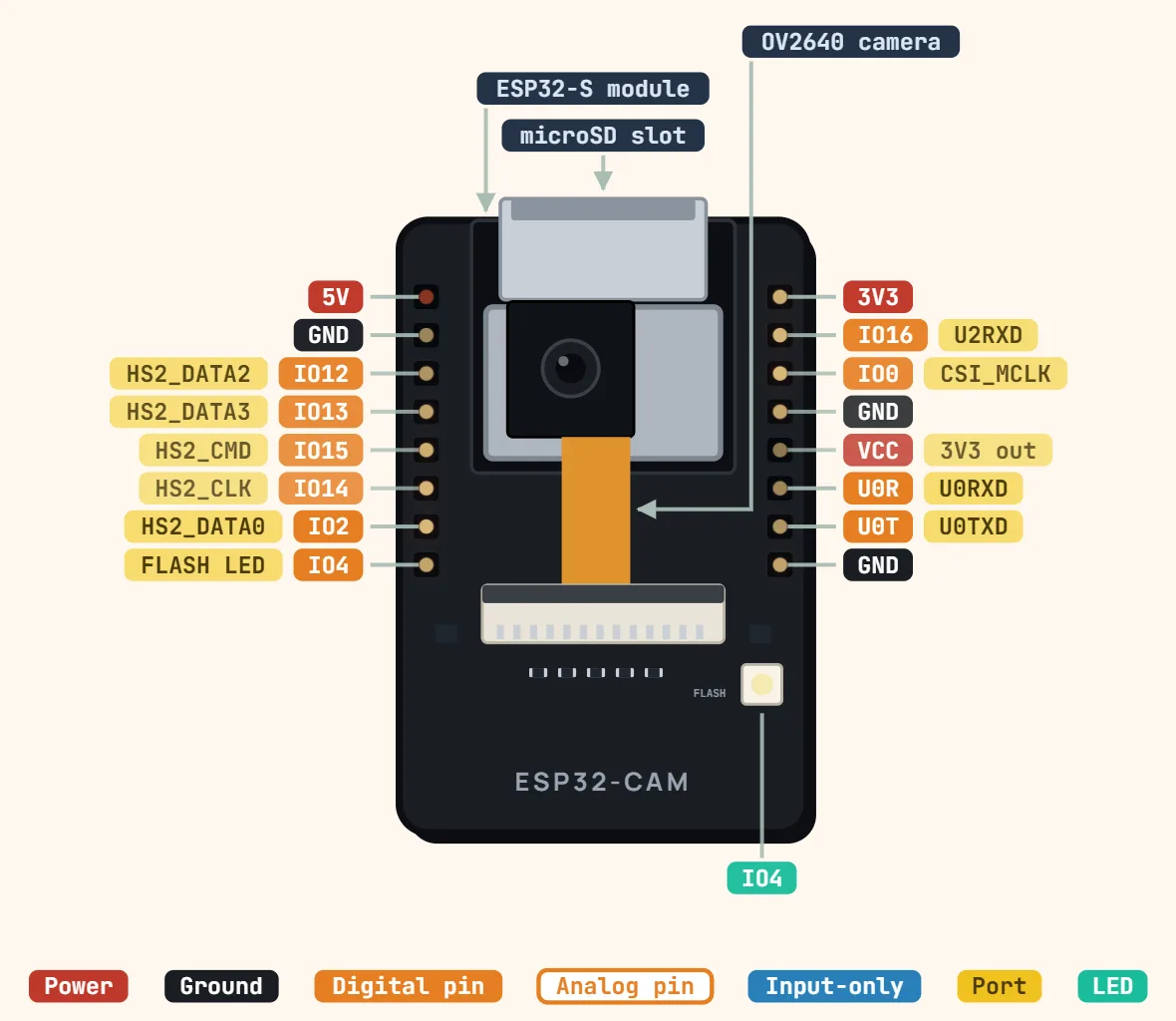
Pins
- 5V
- GND
- IO12 — HS2_DATA2
- IO13 — HS2_DATA3
- IO15 — HS2_CMD
- IO14 — HS2_CLK
- IO2 — HS2_DATA0
- IO4 — FLASH LED
- 3V3
- IO16 — U2RXD
- IO0 — CSI_MCLK
- GND
- VCC — 3V3 out
- U0R — U0RXD
- U0T — U0TXD
- GND
Specifications
| Chip | ESP32 (dual-core, up to 240 MHz) |
|---|---|
| PSRAM | 4 MB |
| Flash memory | 4 MB |
| Camera | OV2640, 2 MP (up to 1600 × 1200) |
| Supply | 5 V on the 5V pin (stable supply; Wi-Fi + camera peaks) |
| Logic level | 3.3 V |
| Wi-Fi | 802.11 b/g/n, 2.4 GHz |
| Bluetooth | v4.2 + BLE |
| Storage | microSD slot (shares GPIO2, 4, 12–15) |
| USB | None — flash via USB-TTL adapter on U0R/U0T |
| Size | 27 × 40.5 mm |
Notes
- 5V and GND — feed 5V here; the onboard regulator makes the 3.3V, and a weak supply browns the board out mid-capture (the classic "reboots when the camera starts" symptom). VCC on the right-hand row is the regulator’s 3.3V OUTPUT (a solder jumper on some batches switches it to 5V), not a second input.
- U0T (TX) / U0R (RX) are the only serial port, and there is no USB port at all: wire a USB-TTL adapter here to flash, with IO0 tied to GND to enter flash mode — then remove that jumper and press RST (the tactile button is on the underside, beside the card slot) to run.
- Free-ish GPIO: 12, 13, 14, 15, 2 and 4, but the MicroSD slot uses exactly those six (the HS2_* bus), so using the card takes them all. GPIO4 also drives the bright white flash LED. GPIO16 is the PSRAM chip select on this module — leave it alone.
- GPIO12 is a strapping pin: anything pulling it HIGH at reset switches the flash voltage and stops the board booting, so keep it free at power-up even though it is broken out.