Pinout
ESP32-S3 DevKitC-1 pinout
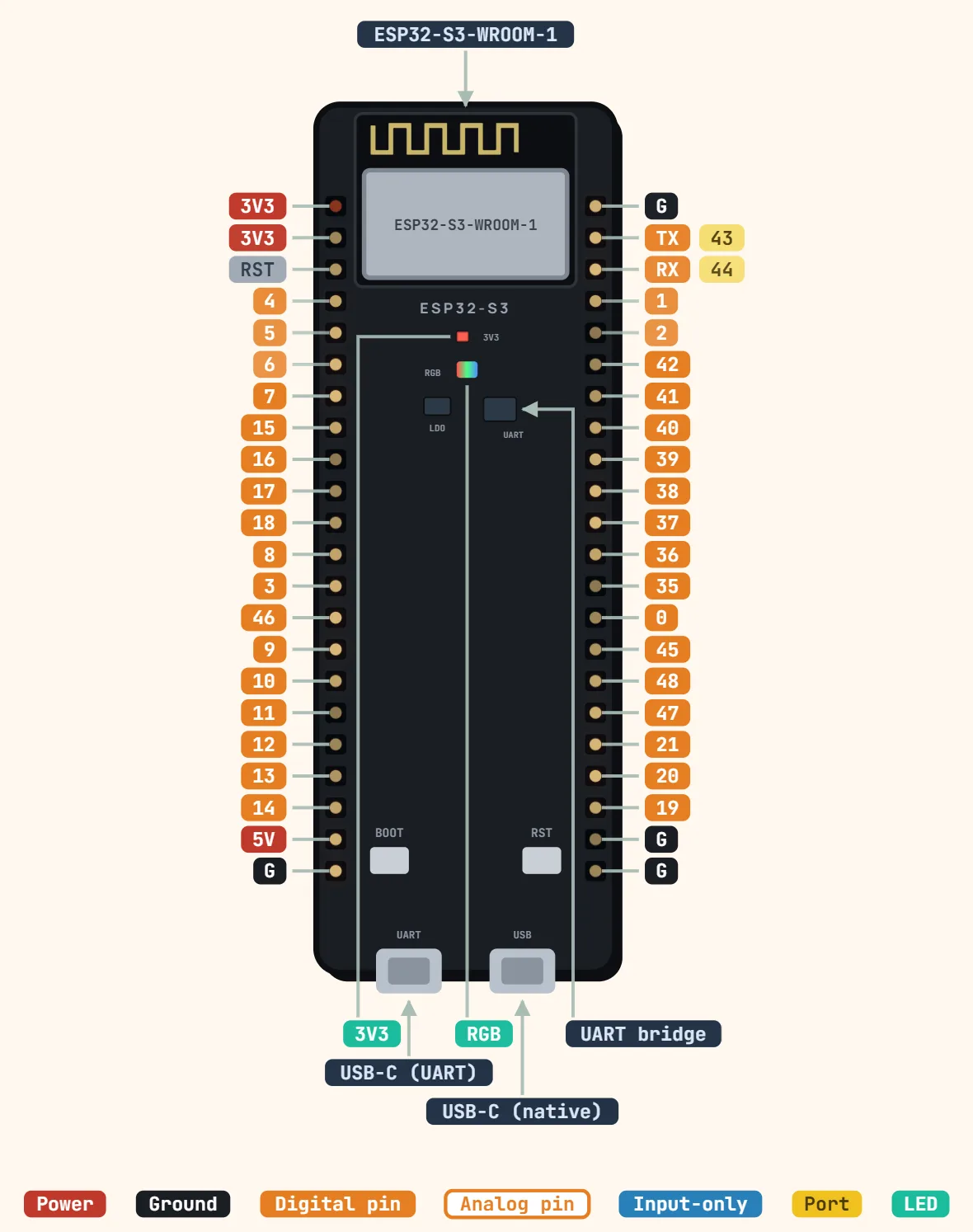
Pins
- 3V3
- 3V3
- RST
- 4
- 5
- 6
- 7
- 15
- 16
- 17
- 18
- 8
- 3
- 46
- 9
- 10
- 11
- 12
- 13
- 14
- 5V
- G
- G
- TX — 43
- RX — 44
- 1
- 2
- 42
- 41
- 40
- 39
- 38
- 37
- 36
- 35
- 0
- 45
- 48
- 47
- 21
- 20
- 19
- G
- G
Specifications
| Module | ESP32-S3-WROOM-1 (or -1U) |
|---|---|
| CPU | Dual-core Xtensa LX7, up to 240 MHz |
| SRAM | 512 KB |
| Flash / PSRAM | Variant-dependent (e.g. N8 = 8 MB flash; N16R8 = 16 MB flash + 8 MB PSRAM) |
| Supply | 5 V via USB or 5V pin, onboard 3.3 V regulator |
| Logic level | 3.3 V (not 5 V tolerant) |
| GPIO current | 40 mA max per pin (strongest drive setting) |
| ADC | 2 × 12-bit SAR, 20 channels (ADC2 unreliable with Wi-Fi) |
| DAC | None |
| Wi-Fi | 802.11 b/g/n, 2.4 GHz |
| Bluetooth | 5 (LE only) |
| USB | 2 × Micro-USB: native USB-OTG/JTAG + USB-UART bridge |
Notes
- The two Micro-USB ports do different jobs and are not interchangeable: the one labeled USB goes straight to the chip's native USB-OTG/JTAG peripheral (GPIO19/GPIO20, not broken out to the header while that port is in use), while the one labeled UART goes through an onboard USB-to-UART bridge chip to the TX/RX pins (GPIO43/GPIO44) — plugging a sketch that only opens the native-USB CDC port into the UART port (or vice versa) is the single most common reason "nothing shows up" on first boot.
- GPIO0 and GPIO46 are sampled together at reset to choose the boot path: GPIO0 low is what asks for download (bootloader) boot instead of the normal app boot, but that only works when GPIO46 is also low — that pairing is Joint Download Boot, which brings up the USB and UART download paths together (there's no separate strapping combination that narrows it to UART-only). GPIO46 needs to be low or left floating, since it's pulled low internally by default; driving it high while GPIO0 is low isn't a documented mode — per Espressif's own esptool docs, GPIO46 must be low or floating for the chip to enter the serial bootloader at all, so pulling it high there blocks download mode rather than restricting which interface it uses. The USB driver's DTR/RTS lines normally toggle GPIO0 and EN automatically during a flash upload, so a manual BOOT+RESET button combo is only needed if that auto-reset handshake fails.
- GPIO45 sets the voltage the internal regulator drives onto VDD_SPI at boot: low (this board's default) means 3.3V flash/PSRAM. Don't wire anything to GPIO45 that could pull it high unless the fitted flash/PSRAM is actually rated for 1.8V — getting this wrong on a 3.3V module can stop the board from booting at all, the same class of failure as GPIO12 on the classic ESP32.
- ADC2 (GPIO11–GPIO20) shares hardware with the Wi-Fi radio, the same limitation carried over from the classic ESP32: readings there become unreliable the moment Wi-Fi is active. Keep any analog reading that must coexist with Wi-Fi on an ADC1 pin (GPIO1–GPIO10) instead.
- Each GPIO's drive current tops out at 40 mA (the strongest of the selectable drive-strength settings, and also GPIO19/GPIO20's default — all other pins default to 20 mA) — the datasheet lists this as a typical DC characteristic, not as a per-pin absolute-maximum rating; the only true absolute-maximum current figure it gives is a cumulative 1500 mA across all I/O pins combined. Either way, treat 40 mA as the practical ceiling per pin — enough for a single LED with its own series resistor, not for a relay coil or a motor winding without a driver stage in between.
- The onboard addressable RGB LED (WS2812) sits on GPIO48 on v1.0 boards and moved to GPIO38 on v1.1 (the current shipping revision) — check which silkscreen revision is printed on your board rather than assuming either pin.
- GPIO26–GPIO32 are routed internally to the module's own SPI flash/PSRAM and not brought out to the header at all; on 16MB-flash/8MB-octal-PSRAM ("N16R8") boards, GPIO33–GPIO37 are lost the same way, so those variants expose noticeably fewer usable GPIO than the bare die's pin count suggests — GPIO35–37 are shown here since the plain header (non-octal-PSRAM) boards do expose them.
- No DAC pins on this chip — unlike the classic ESP32 (DAC1/DAC2 on GPIO25/GPIO26), the S3 has no analog-output peripheral at all; fake one with a PWM pin through an RC low-pass filter, or add an external DAC breakout.