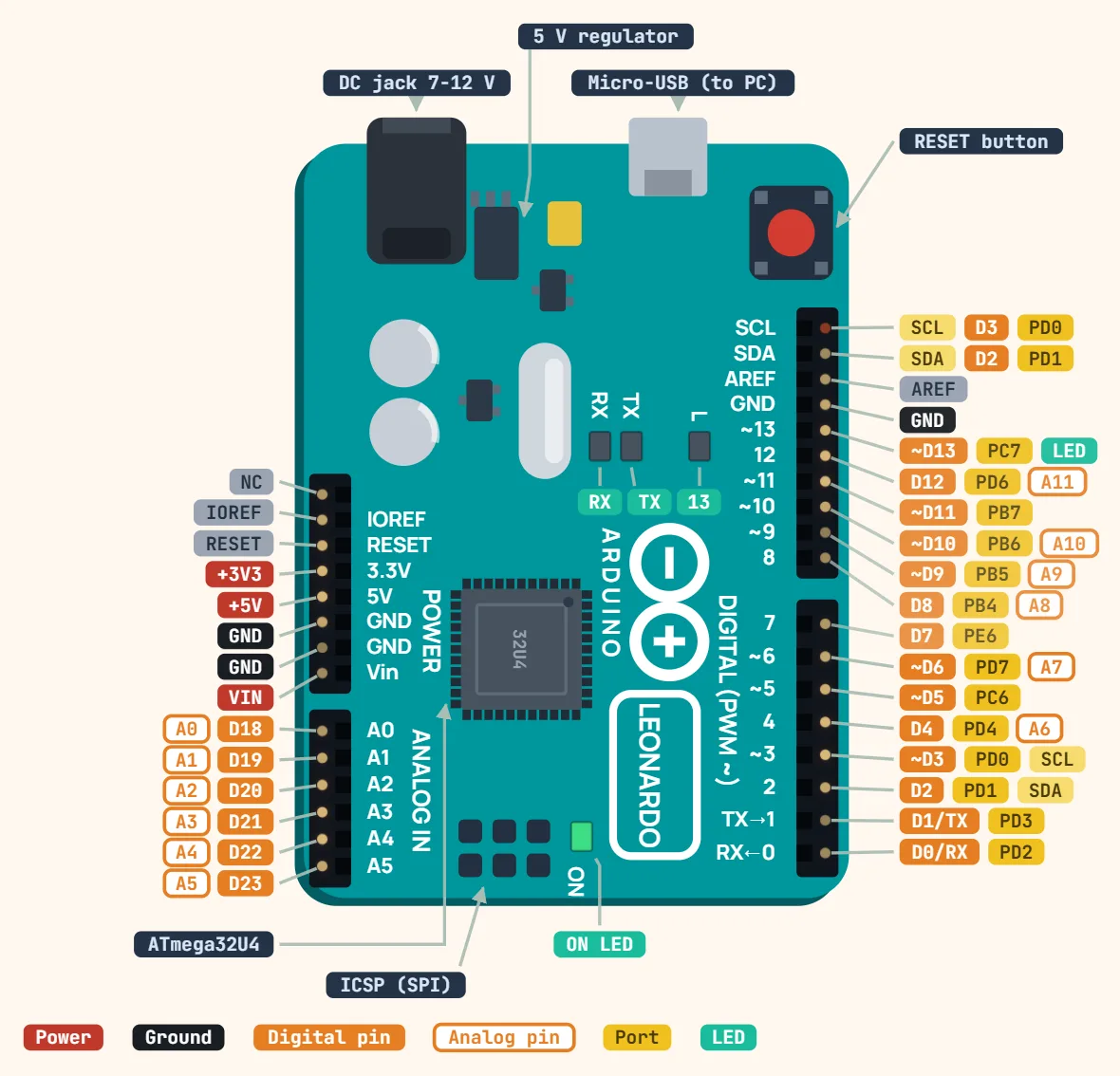
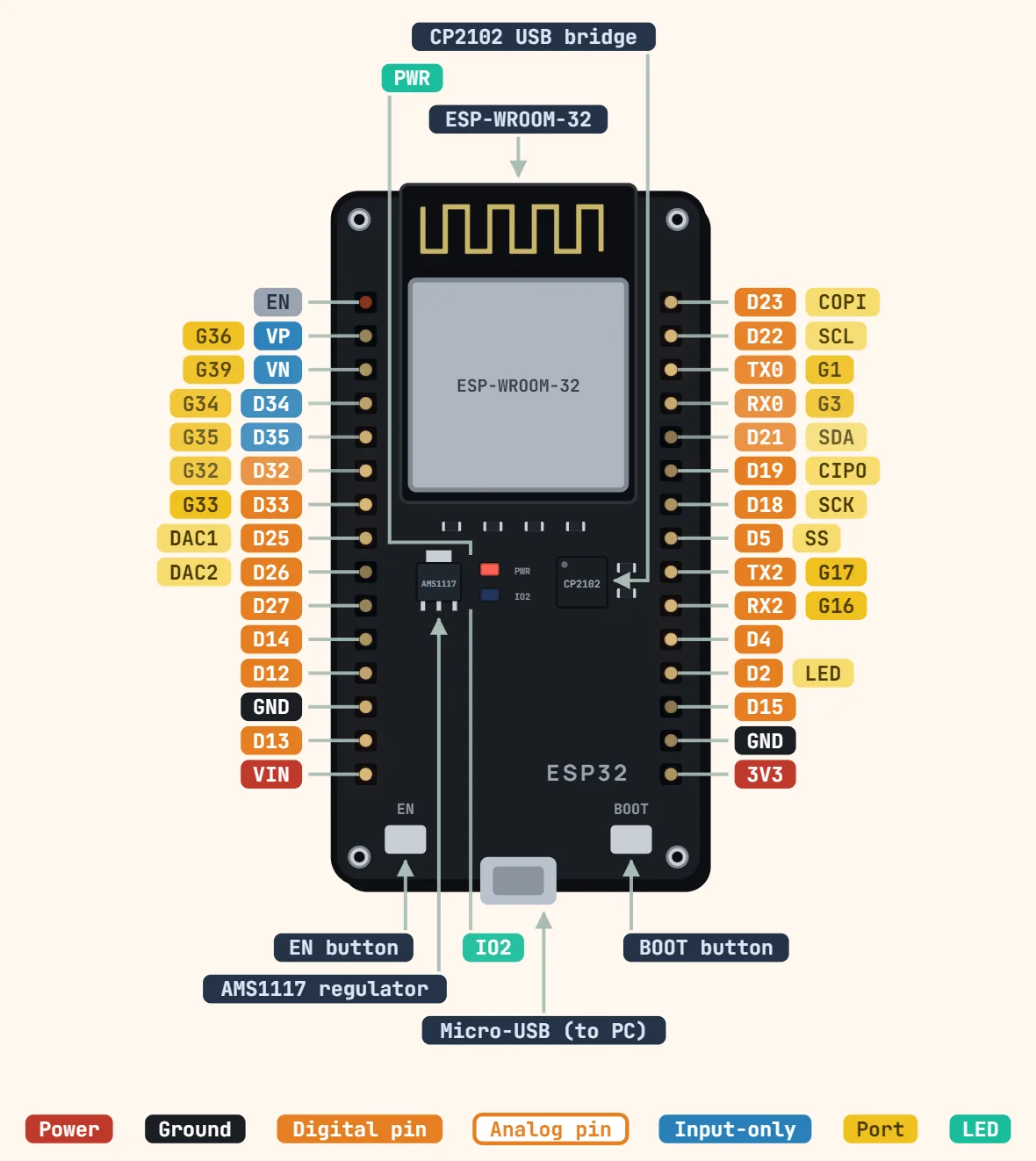
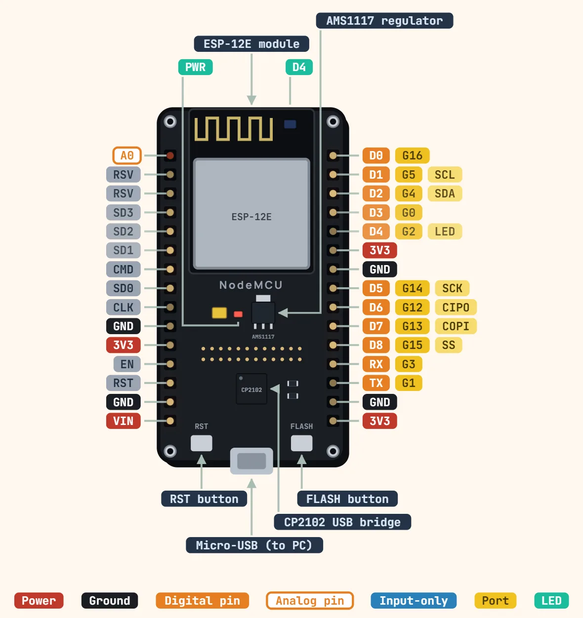
Pinout
Arduino Mega 2560 Rev3 pinout
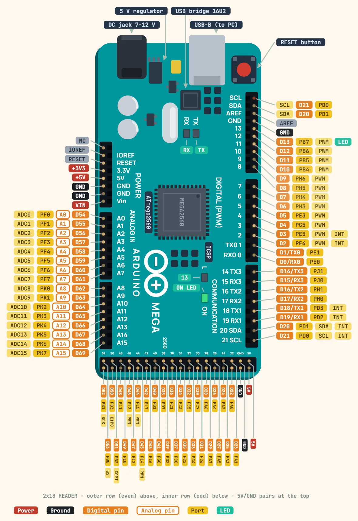
Pins
- NC
- IOREF
- RESET
- +3V3
- +5V
- GND
- GND
- VIN
- D54 — A0 — PF0 — ADC0
- D55 — A1 — PF1 — ADC1
- D56 — A2 — PF2 — ADC2
- D57 — A3 — PF3 — ADC3
- D58 — A4 — PF4 — ADC4
- D59 — A5 — PF5 — ADC5
- D60 — A6 — PF6 — ADC6
- D61 — A7 — PF7 — ADC7
- D62 — A8 — PK0 — ADC8
- D63 — A9 — PK1 — ADC9
- D64 — A10 — PK2 — ADC10
- D65 — A11 — PK3 — ADC11
- D66 — A12 — PK4 — ADC12
- D67 — A13 — PK5 — ADC13
- D68 — A14 — PK6 — ADC14
- D69 — A15 — PK7 — ADC15
- SCL — D21 — PD0
- SDA — D20 — PD1
- AREF
- GND
- D13 — PB7 — PWM — LED
- D12 — PB6 — PWM
- D11 — PB5 — PWM
- D10 — PB4 — PWM
- D9 — PH6 — PWM
- D8 — PH5 — PWM
- D7 — PH4 — PWM
- D6 — PH3 — PWM
- D5 — PE3 — PWM
- D4 — PG5 — PWM
- D3 — PE5 — PWM — INT
- D2 — PE4 — PWM — INT
- D1/TX0 — PE1
- D0/RX0 — PE0
- D14/TX3 — PJ1
- D15/RX3 — PJ0
- D16/TX2 — PH1
- D17/RX2 — PH0
- D18/TX1 — PD3 — INT
- D19/RX1 — PD2 — INT
- D20 — PD1 — SDA — INT
- D21 — PD0 — SCL — INT
- 5V
- 5V
- GND
- GND
- D22 — PA0
- D23 — PA1
- D24 — PA2
- D25 — PA3
- D26 — PA4
- D27 — PA5
- D28 — PA6
- D29 — PA7
- D30 — PC7
- D31 — PC6
- D32 — PC5
- D33 — PC4
- D34 — PC3
- D35 — PC2
- D36 — PC1
- D37 — PC0
- D38 — PD7
- D39 — PG2
- D40 — PG1
- D41 — PG0
- D42 — PL7
- D43 — PL6
- D44 — PL5 — PWM
- D45 — PL4 — PWM
- D46 — PL3 — PWM
- D47 — PL2
- D48 — PL1
- D49 — PL0
- D50 — PB3 — CIPO
- D51 — PB2 — COPI
- D52 — PB1 — SCK
- D53 — PB0 — SS
Specifications
| Microcontroller | ATmega2560 |
|---|---|
| Operating voltage | 5 V |
| Input voltage (recommended) | 7–12 V |
| Input voltage (limit) | 6–20 V |
| Digital I/O pins | 54 (15 PWM) |
| Analog input pins | 16 |
| Hardware serial ports | 4 |
| DC current per I/O pin | 20 mA (40 mA absolute max) |
| DC current for 3.3 V pin | 50 mA |
| Flash memory | 256 KB, of which 8 KB used by bootloader |
| SRAM | 8 KB |
| EEPROM | 4 KB |
| Clock speed | 16 MHz |
| USB | Type-B, ATmega16U2 USB-serial |
| Size | 101.5 × 53.3 mm |
Notes
- Logic is 5V, not 3.3V — unlike most of today’s dev boards (ESP32, Pico and Blue Pill all run 3.3V logic), so a sensor library written for one of those assumes the wrong level on a Mega.
- Four independent hardware UARTs: Serial (D0/D1, shared with the USB-to-serial chip), Serial1 (D19/D18), Serial2 (D17/D16), Serial3 (D15/D14) — a GPS, a Bluetooth module and a debug console can each get a dedicated port instead of fighting over one with SoftwareSerial.
- Only 15 pins do PWM: D2–D13 plus D44–D46. analogWrite() on any other digital pin compiles and runs without error — it just does nothing.
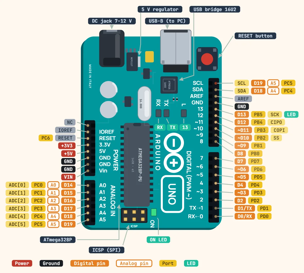
- The SCL/SDA pins next to AREF are the SAME I2C bus as D20/D21, not a second one — brought out a second time the way the Uno R3 does it, so a shield can reach I2C without claiming the dedicated header pins.
- 40mA absolute maximum per I/O pin (the same ATmega-family limit as the Uno/Nano’s 328P), but the total is NOT one flat 200mA across all 54 pins — the datasheet budgets it per port group instead (most groups cap at 200mA, one group at 100mA). Either way, the board’s 5V rail from USB can’t supply anywhere near the theoretical per-pin maximum to every pin at once — budget the total draw, not just each pin in isolation.