Pinout
BNC connector pinout
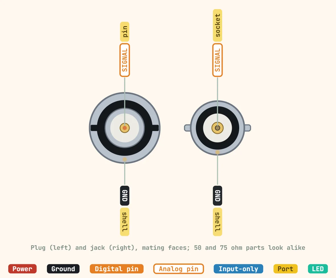
Pins
- Center pin — the signal conductor: a protruding pin on the male plug, a recessed socket on the female jack that the pin seats into
- Outer shell/barrel — shield and ground return: bonds to the cable's braid or foil shield and to the mating jack's shell, carrying the signal's return current as well as chassis/RF ground
Specifications
| Contacts | 2 (centre pin, shell) |
|---|---|
| Impedance | 50 Ω (test gear, RF) or 75 Ω (video, SDI) |
| Coupling | Quarter-turn bayonet |
| Frequency range | DC–4 GHz (typical datasheet) |
| Working voltage | ≈ 500 V RMS (typical datasheet) |
| Mating cycles | 500 (typical datasheet) |
| Scope input | 1 MΩ ∥ ≈ 15–20 pF, or 50 Ω when switched |
| Typical cable | RG-58 (50 Ω), RG-59 (75 Ω) |
Notes
- BNC comes in two electrically incompatible impedances that look almost identical: 50Ω is the default for oscilloscope probes, spectrum analyzers, function generators and most RF test gear, while 75Ω is the video/broadcast standard (composite video, SDI). The two differ in the center pin's diameter and dielectric; forcing a 75Ω plug into a 50Ω jack (or the reverse) can bend or loosen the center pin, and even a clean mate leaves an impedance step that reflects more signal the higher the frequency or bit rate — barely visible on a slow composite signal, much more visible as ringing or ghosting on SDI or a fast pulse.
- The outer ring locks with a quarter turn against two lugs, not threads like SMA/TNC/N-type — quick to connect on a bench, but rated for far fewer mate/unmate cycles than a threaded connector before the lock and center-pin contact start to feel loose; a commonly cited figure is on the order of 500 cycles for a standard connector.
- Typical commodity BNC connectors are specified around 500V RMS working voltage and a few amps of current — treat that as a rough datasheet-typical figure, not a guarantee, since BNC is built as a signal connector and should be derated heavily for anything resembling a power application. Frequency performance varies a lot with build quality too: generic BNC is commonly rated to roughly 4GHz, while precision-machined 50Ω versions are sold rated into the low double-digit GHz range.
- Most oscilloscope BNC inputs default to a high-impedance ≈1MΩ (with a small, typically ≈15–20pF, parallel capacitance) rather than 50Ω — feeding a fast-edged, 50Ω-source-terminated signal into a 1MΩ input without switching the scope (or adding an external 50Ω terminator) causes reflections that show up as ringing or a doubled-amplitude step on the displayed waveform.