Reference sheet
Thermal management
Tj, θJA, and when a part needs copper or a heatsink
Thermal management basics
A part's datasheet gives three different temperatures, and they are not interchangeable. Junction temperature (Tj) is the actual die temperature and the number the part's rated maximum protects, but it's almost never something you can measure directly. Case temperature (Tc) is measurable, at the package's outer surface, and ambient temperature (Ta) is the air around it. Tj always sits above Tc, which sits above Ta, and the gaps between them are what thermal resistance ratings describe.
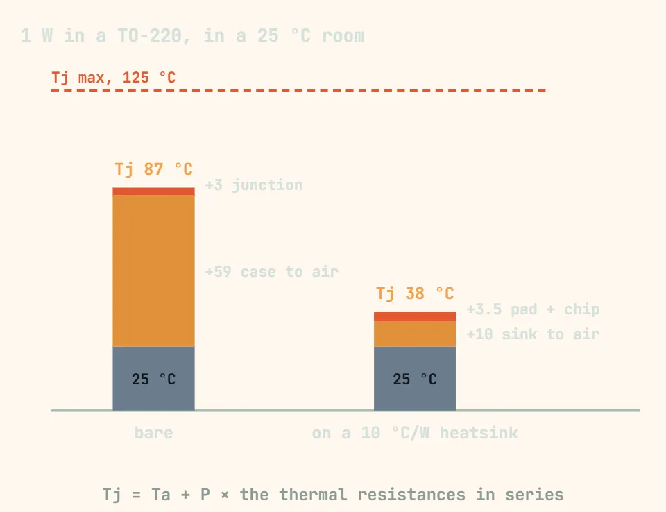
A thermal resistance rating, written as theta (θ) in degrees C per watt, is simply how many degrees the temperature rises for every watt of power flowing through that part of the thermal path. θJA covers the whole junction-to-ambient path with no added heatsink; θJC covers only junction-to-case. The rough estimate most people reach for is Tj ≈ Ta + P × θJA — plug in your worst-case ambient and the power the part actually dissipates, then compare the result against the part's maximum rated Tj, leaving real margin rather than designing right up to the limit.
What a part actually needs, in rising order of effort, is usually copper pour first, a thermal interface material plus a heatsink next, and only after that a design built around a manufacturer's derating curve or active throttling. A small logic IC or lightly loaded regulator is often fine on copper alone; an exposed-pad package needs thermal vias down to that copper to get any benefit from it at all; and once the numbers say a part will run close to its Tj max at your worst-case ambient, an actual heatsink — sized from the calculated temperature rise, not guessed — is what closes the gap.
| Term | What it means | Typical value / rule of thumb | Practical guidance |
|---|---|---|---|
| Junction temperature (Tj) | The temperature at the hottest point inside the die itself — the number every other rating exists to protect. | Absolute max Tj is commonly 125–150°C for standard commercial/industrial silicon, up to 175°C on automotive-grade (AEC-Q100) parts — always check the specific datasheet, it varies by manufacturer and process. | You can't measure Tj directly in most designs; it's calculated from dissipated power and thermal resistance, or occasionally read back from an internal sensor on more advanced parts. |
| Ambient temperature (Ta) | The air temperature actually surrounding the part inside its final enclosure — not the datasheet's 25°C test condition, and not the temperature of the room you're testing in. | Datasheet specs are usually given at Ta = 25°C; real operating ranges commonly span 0–70°C (commercial) or −40 to 85°C (industrial) grades. | Use the worst case you expect in service — inside a closed enclosure, in direct sun, next to another hot component — not bench conditions. |
| Case temperature (Tc) | The temperature at the outside surface of the package (often the top mold cap or an exposed metal tab/pad), a few degrees below Tj. | Sits between Tj and Ta; how close to Tj depends on θJC being small relative to the rest of the path. | The one temperature you can actually measure on the bench, with a thermocouple or IR thermometer — use it to sanity-check a θJA estimate against reality. |
| θJA — junction-to-ambient thermal resistance | Total resistance to heat flow from the junction out to the surrounding air, with no added heatsink, in °C per watt dissipated. | Roughly 150–300°C/W for a bare SOT-23, ~100–160°C/W for a SOIC-8, ~60–65°C/W for a free-standing TO-220, ~30–45°C/W for an exposed-pad QFN/DFN with good thermal vias — figures vary a lot by manufacturer and test board. | Datasheet θJA is measured on a specific standard test PCB (often a JEDEC reference layout) with defined copper area — your own board's copper, layer count and airflow can shift the real number well away from that in either direction. |
| θJC — junction-to-case thermal resistance | Resistance from the junction to the case surface only — it excludes the case-to-ambient path, so it's always a much smaller number than θJA. | Commonly 1–5°C/W for a TO-220-class package, often under 1°C/W for larger tabs like TO-247 or D2PAK — always device-specific. | Used when adding an external heatsink: total resistance becomes θJC + θCS (interface material) + θSA (heatsink to air), added in series. |
| Rough temperature-rise estimate | The back-of-envelope formula for how hot a part gets: Tj ≈ Ta + (power dissipated × θJA). | Example: 0.5 W through a 150°C/W SOIC-8 at 40°C ambient ≈ 40 + 0.5×150 = 115°C junction temperature. | Treat this as a steady-state estimate, not a guarantee — it ignores thermal mass and transients and assumes the datasheet's test-board copper area, so leave real margin below the absolute max rating rather than designing right up against it. |
| Copper pour as a heat spreader | Using the PCB's own copper (top, bottom, or an inner plane) to carry heat away from a package instead of adding a separate part. | Effective up to roughly 1–2 W for small packages; a larger poured area (several cm², especially tied to an inner ground/power plane) measurably lowers θJA. | The cheapest thermal fix there is, and often enough on its own for logic ICs, small regulators and low-power MOSFETs — try this before reaching for a heatsink. |
| Thermal vias | An array of small plated vias under an exposed thermal pad (QFN, DFN, PowerPAD-style packages), conducting heat through the board to copper on another layer. | Commonly a grid of roughly 0.3 mm vias on about a 1–1.2 mm pitch, sometimes plated shut to stop solder wicking away during reflow. | Follow the part's land-pattern application note for via count and spacing — too few vias, or an exposed pad left unconnected, is a very common reason a QFN runs hotter than its datasheet θJA suggests. |
| Thermal interface material (TIM) / thermal pad | A gap-filling layer (silicone pad, grease/paste, graphite sheet) between a component and a heatsink or chassis, replacing the air gap that would otherwise dominate the path. | Thermal conductivity is commonly in the rough range of 1–8 W/m·K for everyday pads and pastes; specialty materials can go higher — conductivity varies enormously by product, so check the specific datasheet. | A TIM isn't a heatsink by itself — it only cuts the contact resistance at an interface, so it's used together with, not instead of, a heatsink or metal enclosure that can actually carry the heat away. |
| Dedicated heatsink | An added finned or extruded metal part that increases the surface area exposed to air, cutting the case/board-to-ambient resistance (θSA). | Small clip-on or adhesive-backed heatsinks commonly run roughly 5–30°C/W in natural convection (smaller / fewer fins = higher number); adding a fan typically cuts that by half or more. | Needed once the copper-pour/TIM estimate still pushes Tj close to, or over, the part's rated maximum at worst-case ambient — size it from the calculated temperature rise, with margin, not from what physically fits. |
| Power derating curve | A datasheet chart showing the maximum allowed power dissipation falling as ambient temperature rises, in place of a single θJA figure. | Often flat (full rated power) up to some ambient, e.g. 25–50°C, then a roughly straight-line derate down to zero allowed power at Tj max. | This curve is the more accurate design tool once you're operating anywhere near the top of a part's ambient range — a single θJA number is really just a convenient approximation of one point on it. |
| Active thermal throttling | Runtime protection built into many digital/power parts (MCUs, power converters, motor drivers) that reduces clock speed, output current or duty cycle as Tj nears its limit, instead of letting the part fail outright. | Thresholds and behavior are part-specific — some throttle in graduated steps, others simply shut down (thermal shutdown / OTP) at a fixed Tj and restart after cooling, with hysteresis. | Throttling protects the silicon, not your application — a design that relies on it to stay within its thermal budget will just perform worse (slower, less output current) exactly when full performance was needed. |
θJA numbers on a datasheet are measured on a specific standard test board (often a JEDEC reference layout) — your own board's copper area, layer count and airflow can move the real value well away from that figure, so treat any Tj estimate as a starting point and check it against an actual thermocouple or IR measurement under real load.