Interactive simulation
PWM + RC filter simulation
Duty cycle through a low-pass — the DAC every microcontroller has.
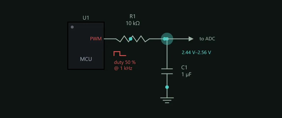
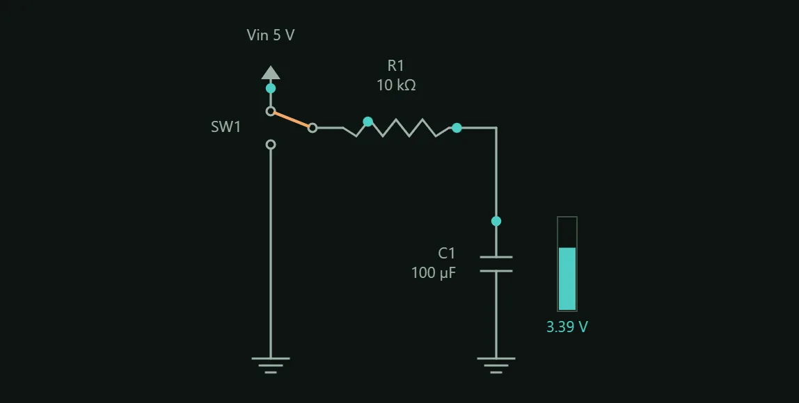
An RC low-pass turns a PWM square wave into a DC level of 5 V × duty — the poor man's DAC. Push f well above fc (or raise R and C) and watch the teal ripple collapse onto the dashed average. The dots run forwards while the pin is high and backwards while it is low: over a period no net charge crosses the capacitor, which is exactly why the output holds a steady average instead of drifting away. At 0 % and 100 % duty they stop — there is nothing left to charge. Raising R and C to kill ripple is not free, though: drag Duty and watch the dashed average line take real time — the settling time above — to slide to its new position, not jump there. Nothing lands and holds here: a PWM filter is periodic, so it runs for as long as the panel is open.
What you can change
- Frequency
- R
- C