Interactive simulation
Op-amp gain & clipping simulation
Raise the gain until the sine flattens against the rails.
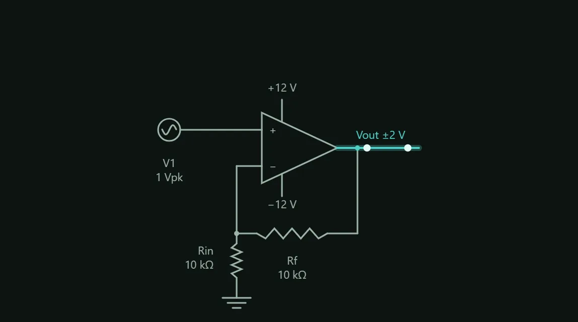
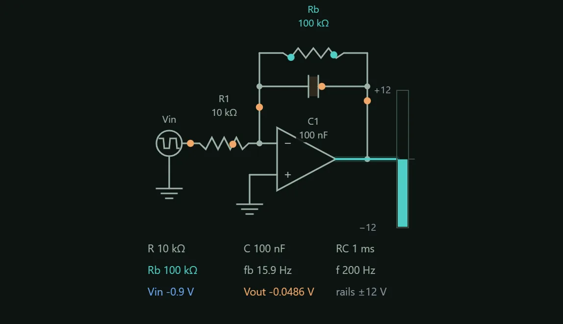
Raise the input amplitude or the gain until the sine's head flattens against the rails — that flat top is what distortion sounds like. A real op-amp loses ~1.5 V to each supply rail (rail-to-rail parts get much closer), which is where the dashed clip lines sit — not at the rail itself. The sketch above rewires itself per mode; its output lead glows teal, turns red the instant the wave clips, and its dots run out, stall and run back with the output's own half cycles. The 1 kHz input is fixed, but raising the closed-loop gain shrinks the closed-loop bandwidth (GBW ÷ gain) right past it — the output visibly shrinks instead of clipping. Push the required slew rate (2π × frequency × amplitude × gain) past the Slew rate dial instead, and the sine turns into a straight-sided triangle well short of the rails — a distinct shape from a clipped flat top, and a distinct cause.
What you can change
- Input amplitude
- Rf
- Rin
- Supply rail ±