Reference sheet
Relay contacts
SPDT, NO / NC, coil voltages and the flyback diode
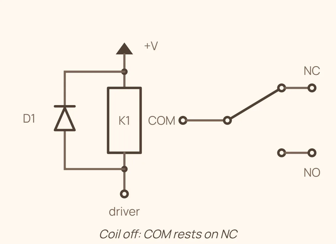
Relay contact types & ratings guide
A relay is an electromechanical switch: current through a coil creates a magnetic field that pulls an armature, which moves one or more sets of contacts. Poles count how many separate circuits the relay switches at once, and throws count how many positions each pole can land on. NO (normally open) and NC (normally closed) describe a contact's state with the coil de-energized — NO is open at rest and closes when the coil pulls in, NC is closed at rest and opens when the coil pulls in.
The coil side and the contact side are electrically isolated from each other, which is the whole point of a relay: a low-power logic signal on the coil can switch a much higher-power or higher-voltage circuit on the contacts without the two ever touching. That also means coil voltage and contact rating are two independent specs you have to check separately on any relay you're reverse-engineering — a small coil voltage says nothing about how much current the contacts can carry.
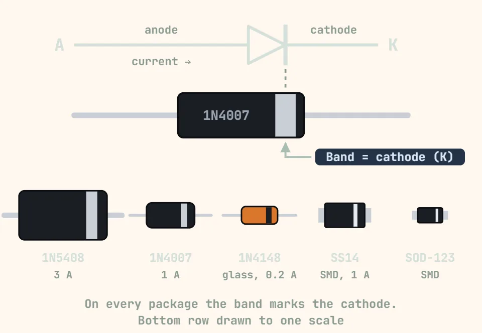
When a DC relay's coil is switched by a transistor or a microcontroller pin (rather than a simple mechanical switch), the coil's inductance causes trouble the instant it's turned off: the collapsing magnetic field induces a large reverse voltage spike that can destroy the driving transistor. A diode wired across the coil gives that current somewhere safe to go — this is covered in the table below.
| Category | Type / value | Typical numbers & notes |
|---|---|---|
| Contact arrangement | SPST-NO (Form A) | 1 pole, 1 throw, normally open ("make" contact). Open with the coil de-energized, closes when energized. Two terminals: COM and NO. |
| Contact arrangement | SPST-NC (Form B) | 1 pole, 1 throw, normally closed ("break" contact). Closed with the coil de-energized, opens when energized. Two terminals: COM and NC. |
| Contact arrangement | SPDT (Form C) | 1 pole, 2 throws — a change-over contact. Three terminals: COM, NO and NC; COM rests on NC and swings to NO when the coil pulls in. The most common arrangement on small PCB relays. |
| Contact arrangement | DPDT / 3PDT / 4PDT | Two, three or four independent Form-C (SPDT) contact sets ganged onto one coil and switched together. DPDT is often used to reverse a motor's polarity by cross-wiring the two poles, or to switch two unrelated circuits at once. |
| Coil voltage | Low-voltage DC (5V / 6V / 9V / 12V / 24V) | Most common on signal and small PCB relays. Coil resistance is commonly in the tens to low hundreds of ohms, drawing roughly tens of mA — usually too much for a microcontroller GPIO pin to source directly, so the coil is switched through a transistor, MOSFET, or driver IC (e.g. a ULN2003). |
| Coil voltage | AC coils (24V / 120V / 230V AC) | Used on contactors and industrial/HVAC control relays, often driven straight from mains or a control transformer. No flyback diode is used here (a diode would only conduct on the negative half-cycle) — an RC snubber or MOV is used instead if arc suppression is needed. |
| Contact rating | Signal-level (reed / gold-flashed contacts) | From a few mA up to roughly 1A at low voltage. Gold-flashed contacts are used because at very low current there isn't enough arcing to break through the oxide film that plain silver contacts build up ("dry" or cold switching). |
| Contact rating | Small PCB power relay | Commonly rated around 5-10A at 250VAC or 28-30VDC for a resistive load — but the DC rating on the same relay is typically much lower, since DC has no zero-crossing to help extinguish the switching arc. Inductive loads (motors, solenoids) de-rate the contacts further; check the datasheet's inductive-load column, not just the resistive number. |
| Contact rating | Automotive / high-current relay | Typically 20-40A at 12-14VDC (some models higher), the common SPDT relay found in car fuse/relay boxes for fans, horns, lighting and pumps. |
| Coil protection | Flyback (freewheeling) diode | Wired in reverse bias directly across a DC relay's coil — cathode toward the supply, anode toward the node the driver transistor pulls low. When the transistor switches off, the coil's collapsing field induces a reverse spike (V = -L·di/dt) that can reach tens to hundreds of volts; without a path for that current, it usually punches through the transistor's breakdown voltage. The diode clamps the spike and lets the coil current recirculate and decay safely. Typical parts are 1N4001-1N4007 for small relays or 1N4148 for very small signal relays, sized to the coil's continuous current. It does slightly slow the relay's release time, which is normal. |
These are typical, order-of-magnitude figures — coil resistance, coil current, and especially contact ratings vary a lot between manufacturers and even between series from the same maker, so always confirm against the datasheet for the exact part number printed on the relay rather than designing to these numbers. When reverse-engineering a board, a missing flyback diode next to a relay driven by a transistor is a real red flag (or the diode may just be hidden underneath the relay footprint) — and don't assume the coil polarity from pin position alone, since it isn't standardized across manufacturers.