Reference sheet
Crystal load capacitors
Size C1 and C2 from the crystal's CL, and why it matters
Crystal load capacitance guide
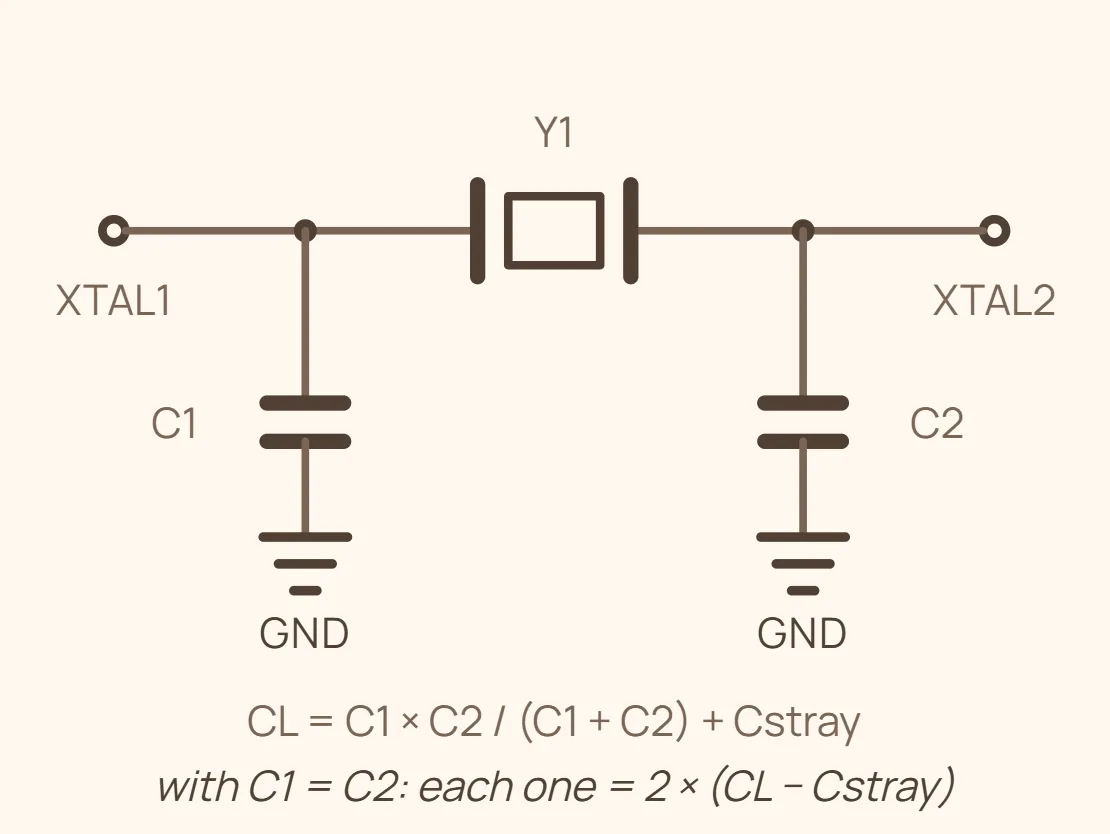
A crystal only sits on its printed frequency when the total capacitance its two pins see - the oscillator's load capacitance, CL - matches the value the manufacturer trimmed it against. That CL is not one part: it is the combination of the two discrete capacitors wired from each crystal pin to ground plus the stray capacitance already present from PCB traces, pads, and the IC's own pins. Get the combination wrong and the crystal keeps oscillating, just not quite on frequency.
For the standard two-capacitor Pierce circuit found on almost every MCU crystal, the relationship is CL = (C1 x C2)/(C1 + C2) + Cstray. Since C1 and C2 are almost always chosen equal in practice, this reduces to C = 2 x (CL - Cstray), where C is the value of each capacitor. Cstray - the trace, pad, and pin capacitance the two crystal pins see beyond the discrete caps - typically runs about 3-5pF on a compact board, but it depends on layout and the specific IC, so treat it as a starting estimate and confirm against the host chip's datasheet when one is available.
Using a different effective load capacitance than the crystal was trimmed for pulls the frequency off nominal in a predictable direction: too much load capacitance pulls the frequency down, too little pulls it up. The size of the shift is usually a few to a few tens of parts-per-million per picofarad of mismatch for a typical crystal - small enough that plain digital logic shrugs it off, but large enough to matter for an RTC's timekeeping drift or a clock feeding USB or a radio, where the tolerance budget is tight.
| Crystal's rated CL | External cap per leg (C1 = C2), Cstray ≈ 3-5pF | Nearest standard cap value | Typical crystal type |
|---|---|---|---|
| 6pF | 2-6pF | ≈3-5pF, or sometimes omitted entirely | Ultra-low-power 32.768kHz watch/RTC crystals - a rare, low-CL rating chosen to cut oscillator drive power |
| 7pF | 4-8pF | ≈6.8pF | Low-power 32.768kHz RTC crystals, common in battery-powered designs |
| 9pF | 8-12pF | 10pF | 32.768kHz RTC crystals - a manufacturer's low-CL alternative to 12.5pF |
| 12.5pF | 15-19pF | 18pF (some designs use less if the MCU's own pin capacitance is high) | The de-facto standard rating for 32.768kHz watch/RTC crystals |
| 15pF | 20-24pF | 22pF | Some 32.768kHz crystals and a handful of lower-frequency MHz parts |
| 18pF | 26-30pF | 27pF (30pF also common) | Classic HC-49/HC-49U through-hole MHz crystals (8, 12, 16MHz, etc.) - a long-standing default |
| 20pF | 30-34pF | 33pF | Widely used default for SMD MHz crystals in modern MCU designs |
| 22pF | 34-38pF | 33pF or 39pF, both standard values | Alternative common MHz rating, largely interchangeable with 20pF parts |
| 30pF | 50-54pF | 47pF or 56pF depending on manufacturer | Less common; some legacy or higher-frequency parallel-resonant crystals |
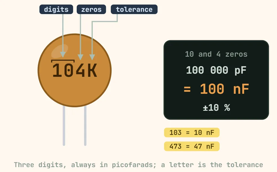
If you can't read the crystal's markings, don't guess a "standard" CL - the same package and footprint ship in several CL variants, so measure the two board capacitors (or read their printed code) instead. And whatever value you land on, keep C1 and C2 equal to each other: an unequal pair unbalances the oscillator's duty cycle more than a modest CL error shifts the frequency.