21 October 2026
Reading a MOSFET Datasheet: Vgs(th) vs the Gate Voltage You Actually Apply
Vgs(th) is where a MOSFET just begins to conduct, not where it switches fully on. Here is how to compare it with the gate voltage on your bench and avoid a part that runs hot.
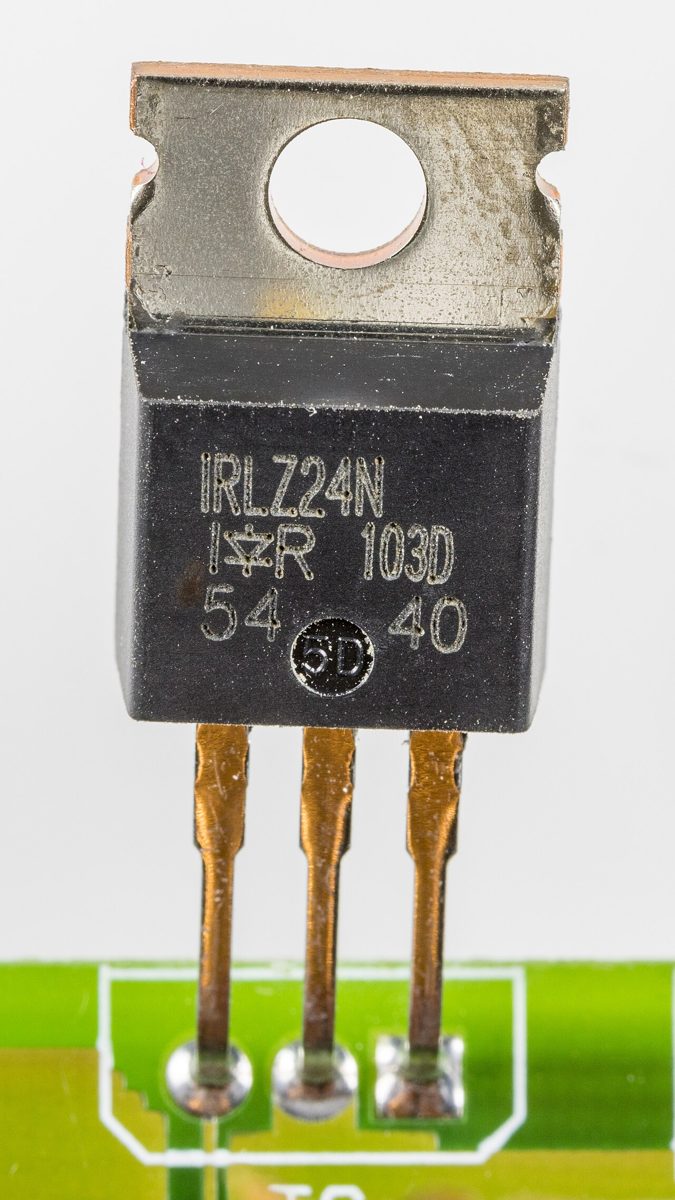
Why the threshold number matters at the bench
You pick a MOSFET to switch a load on and off from a microcontroller pin or a logic output. The first number most people look at is Vgs(th), the gate threshold voltage. It sounds like the voltage needed to turn the part on, but it is only the point where drain current begins to flow in a measurable way.
If you drive the gate right at that point, the transistor is barely conducting. It behaves like a resistor with a high value, and whatever current passes through it will heat it up. The useful switching region comes well above threshold.
What the test condition actually means
Datasheets specify Vgs(th) at a small test drain current, often a few hundred microamps, with the drain tied to a set voltage. The number describes the point where that small current starts to flow under those conditions, not how the device behaves at ten amps.
Vgs(th) also has a typical value and a minimum and maximum. Parts from the same family can differ noticeably, and the threshold drops as the junction temperature rises. A design that works on a cold bench may behave differently after the part warms up.
A worked example with illustrative numbers
Suppose a logic-level N-channel MOSFET is listed with Vgs(th) typical 1.5 V and maximum 2.5 V. You drive its gate from a 3.3 V microcontroller output. The overdrive, which is the gate voltage above threshold, is 3.3 V minus 1.5 V, giving 1.8 V in the typical case.
In the worst case the overdrive is 3.3 V minus 2.5 V, which is only 0.8 V. The part may conduct, but it sits near the bottom of its curve. The on-resistance, Rds(on), is usually specified at a higher gate voltage such as 4.5 V, and at 0.8 V of overdrive it can be several times larger than the headline figure. Those extra milliohms turn into heat at load current, so a switch that looks fine on paper can run hot on the bench.
These numbers are illustrative only. Check your own part's Rds(on) versus Vgs graph, which shows the trade-off directly.
Bench tip Compare the Rds(on) figure with the gate voltage at which it was measured, and make sure your drive voltage is at or above that value.
Checking the threshold yourself
A variable bench supply makes a simple test possible. Connect the drain through a modest resistor to a supply, put the source at ground, and sweep the gate voltage up slowly while watching the voltage across the drain resistor with a multimeter. The voltage starts to rise when drain current begins, giving a rough sense of where the part turns on.
Keep the gate-source voltage within the absolute maximum rating, and use a resistor in series with the gate so that a mistake does not destroy the part.
Bench tip Add a pulldown resistor from gate to source so the transistor stays off when the microcontroller pin floats during reset.
Practical rules for picking and driving a MOSFET
Choose a part whose Rds(on) is specified at or near the gate voltage you can truly provide. If your logic is 3.3 V, look for a logic-level device with its on-resistance listed at 2.5 V or lower, not one specified only at 10 V.
Remember that a small gate resistor helps control switching edges and ringing, and a pulldown keeps the gate defined. Finally, treat Vgs(th) as the start of the story, and let the on-resistance curve decide whether the switch is good enough for your current.