20 October 2026
Why a Crystal Oscillator Needs Load Capacitors to Hit Its Frequency
A crystal's rated frequency assumes a specific load capacitance. Here is how the two capacitors around it set that load, with a worked example and bench checks.
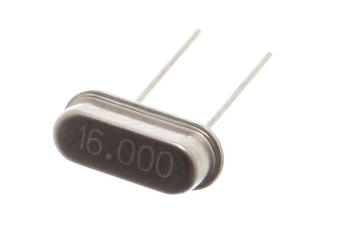
Why the crystal cares what it sees
A quartz crystal used as a frequency reference is not a simple resonator that vibrates at one fixed rate no matter what is connected to it. Its datasheet specifies a load capacitance, the total capacitance the oscillator circuit presents across the crystal's two leads, and the rated frequency is only accurate when the circuit presents that value. Look at the frequency tolerance line on any crystal datasheet and you will usually see a load capacitance condition printed right beside it.
On a real bench this matters because the crystal is only one part of the feedback loop. The oscillator chip or discrete amplifier, the traces, and the pins all add capacitance and feed back into the loop, and the load capacitors are the knob that lets you bring the total to the value the crystal expects. Without them, the crystal may still run, but at a frequency that depends on your particular board layout.
The two-capacitor arithmetic
Most crystal oscillators use two load capacitors, one from each lead to ground. Seen from across the crystal, these two capacitors act in series, so the effective value is their product divided by their sum. Add the stray capacitance of the circuit, which is often a few picofarads, and you get the total load: CL equals C1 times C2 divided by the sum of C1 and C2, plus Cstray.
Here is a worked example. Suppose the datasheet asks for a 18 pF load and you estimate about 3 pF of stray capacitance from the board and the chip. You need the series pair to contribute 15 pF. If you pick C1 and C2 both at 30 pF, the series value is 30 times 30 divided by 60, which is 15 pF. Add the 3 pF stray and the total is 18 pF, which matches the datasheet. If you had picked 22 pF caps instead, the series value would be 11 pF, the total only 14 pF, and the crystal would run high because it sees less load than it was designed for.
Treat the stray value as an estimate. Layout, the oscillator's input and output pin capacitance, and any probe or wire you attach all change it. That is why the capacitor values on a finished schematic are a starting point for the bench, not a final answer.
Bench tip Use the datasheet's stated load capacitance as the target, and remember that the two load caps only need to be equal if the circuit is symmetric. Many designs need unequal values to balance gain.
What goes wrong when the load is off
If the load capacitance is too low, the crystal sees a slightly different reactance than intended and the frequency moves upward. If it is too high, the frequency moves downward. The shift is usually small, often a few parts per million per picofarad near the nominal load, but for a clock that feeds a serial link or a timer that must be accurate, a few ppm can be a real error. The sensitivity is also not linear across the whole range, so the error grows the further you stray from the specified value.
Load capacitance can also affect whether the oscillator starts at all. The amplifier must supply enough gain to overcome the crystal's equivalent series resistance, and very large load capacitors reduce the loop gain and can make startup slow or unreliable, especially at low supply voltage or over temperature. Very large values can also drive the crystal harder than its rated drive level, which can shift frequency and shorten its life. Stay within the range the datasheet and the oscillator chip's documentation recommend.
Bench tip If a crystal starts intermittently on the bench, check the load capacitors and the oscillator's supply decoupling before blaming the crystal itself.
Measuring without fooling yourself
The most common bench mistake is measuring the frequency with a probe that adds its own capacitance. A standard 10x scope probe carries roughly ten to fifteen picofarads of input capacitance, enough to pull a crystal noticeably off frequency. Use a high-impedance, low-capacitance setup, keep the probe lead short, or measure with a frequency counter coupled through a small capacitor or a high-impedance buffer. Whatever you use, measure the frequency and compare it to the datasheet tolerance rather than judging by a single reading.
Pair your measurement with a sanity check on the capacitor values. If the frequency is off and the load caps match the datasheet arithmetic, suspect stray capacitance from the layout or a mismatch in the oscillator itself. Adjust one thing at a time, and write down each value you change so you can see which change moved the frequency.
Bench tip Trim capacitors or a small series variable capacitor make fine adjustment easy on a prototype, but on a final board, choose fixed values once you have measured the real frequency.