19 October 2026
Inductors Resist Changes in Current, Not Current Itself
An inductor does not oppose current; it opposes how fast current changes. That one idea explains coil kick, slow turn-on in circuits, and why a switch can get zapped.
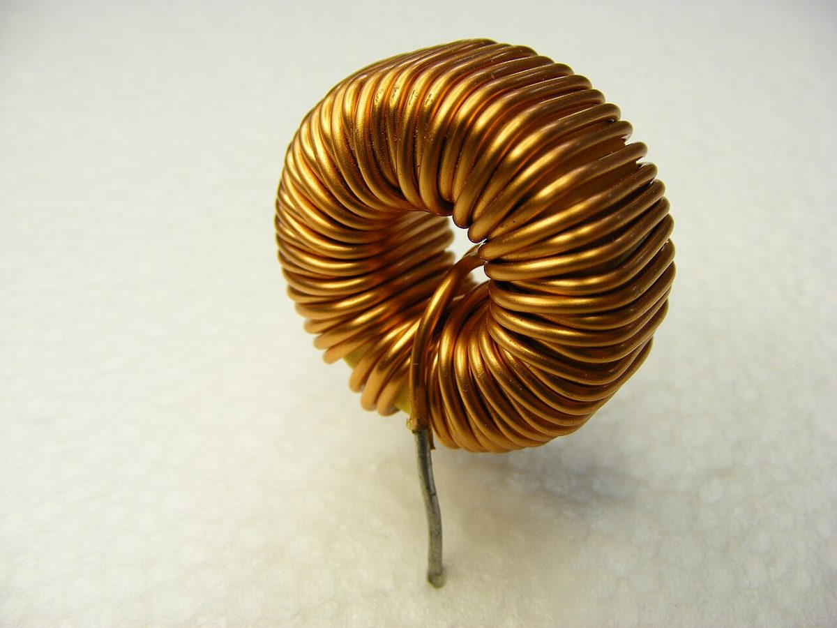
Why this matters on the bench
Most people first meet inductors as a mysterious coil that ruins a square wave or makes a relay click oddly. Once you understand that an inductor is about change, those symptoms stop looking random. A coil in series with a supply slows the turn-on of current. A coil across a switch can produce a voltage spike when the switch opens. Both behaviours come from one relation, and it is worth keeping in your head every time you wire up a motor, relay, or buck converter.
The rule: voltage follows the rate of change
For an ideal inductor, the voltage across it equals the inductance multiplied by the rate of change of current through it. In symbols, v equals L times di/dt. Inductance L is measured in henries, and a typical hobby inductor is somewhere in the microhenry to millihenry range. If the current is constant, di/dt is zero, so the voltage is zero, even if the current is large. The inductor is effectively a short for steady DC. If the current is changing, the inductor produces whatever voltage is needed to push back against that change, with a polarity that tries to keep the current flowing as it was.
This is why the phrase resist a change in current is more accurate than oppose current. The inductor does not care how much current is flowing right now. It cares whether that amount is going up, going down, or holding still.
A worked example with real numbers
Take a 10 mH inductor and ramp its current from 0 to 200 mA over 2 ms. The rate of change is 0.2 A divided by 0.002 s, which is 100 A/s. The voltage across the coil is then 0.01 H times 100 A/s, or 1 V. Hold the current at 200 mA afterwards and the voltage across the coil falls back to zero.
Now compare the energy. Stored energy is one half times L times I squared, so 0.5 times 0.01 H times 0.2 A squared gives 0.2 millijoules. That energy has to go somewhere when the current is interrupted. If you drive the same coil through a series resistor of 100 ohms, the current rises with a time constant of L over R, which is 100 microseconds. In a few hundred microseconds the current has essentially reached its final value, and you can see that on a scope.
Bench tip Before you calculate anything, estimate di/dt from your waveform. A fast edge across a modest coil can produce a surprising voltage.
Switching off a coil safely
When a switch opens in series with an inductor, the current cannot stop instantly, so the voltage across the coil rises until something conducts. The switch contacts, or the transistor driving it, often take the hit. This is the origin of the flyback spike that makes relay drivers fail. The fix is to give the current a path to circulate. A reverse-biased diode across a relay coil clamps the spike to about one diode drop above the supply, and the coil current decays through the diode and the coil resistance.
Snubbers, such as a resistor and capacitor in series or a transient voltage suppressor, do similar work when you need faster decay or a higher clamp voltage. The choice depends on how quickly you need the current to fall and what the driver can tolerate.
Bench tip Put the flyback diode right across the coil terminals, not back at the connector, and check that its polarity is reverse-biased in normal operation.
Keeping the model honest
The ideal relation v equals L di/dt is a good starting point, but real inductors have winding resistance, which may be a few ohms for small parts and much less for power inductors, and parasitic capacitance that makes them resonate at some high frequency. Above that self-resonant frequency, the part stops acting like an inductor. Core material also changes the effective inductance with current and temperature, so a rated value is a nominal figure, not a constant. Check the datasheet for your part's current rating and treat the numbers here as typical ranges.
Bench tip A quick check: measure the DC resistance with your multimeter. If it is far higher than expected, the winding or a joint may be the problem.