17 October 2026
What ESR Means for a Capacitor and Why It Matters in Switching Supplies
Equivalent series resistance decides how much a capacitor really smooths a switching supply's output. A worked example shows why a cap that looks fine on paper can still ripple badly.
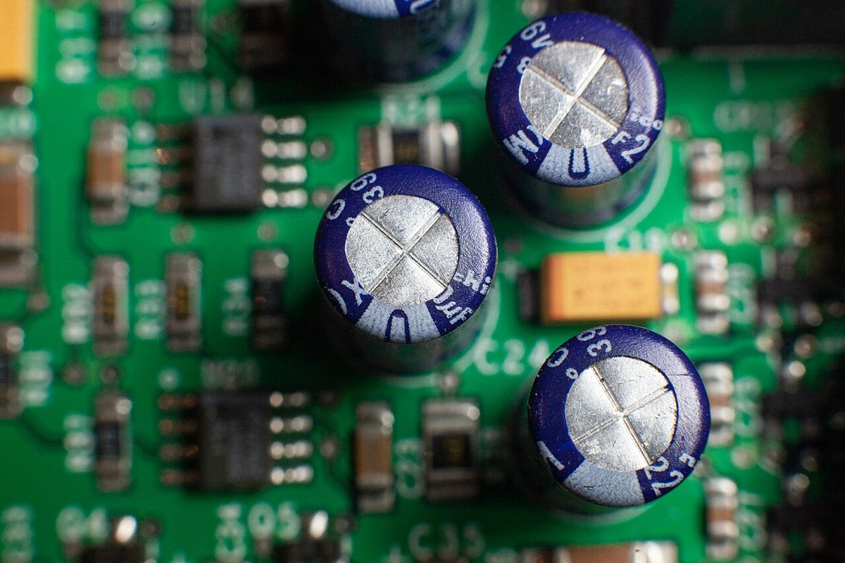
Why ESR shows up on the bench
If you have ever built a buck converter or repaired a bench supply, you have probably seen output ripple that looked much bigger than the capacitor values suggested. The output filter cap was large, the layout looked tidy, and yet the scope still showed a jagged waveform riding on the rail. The usual culprit is not the capacitance but a quiet parameter printed nowhere obvious on the schematic: equivalent series resistance, or ESR.
Understanding ESR changes how you pick filter capacitors and how you diagnose a supply that has gone soft. It explains why two capacitors with identical capacitance and voltage ratings can behave very differently, and why a cap that was perfectly fine five years ago may now be the reason a regulator is running warm.
What ESR actually is
A real capacitor is best modeled as an ideal capacitance in series with a small resistance, plus a tiny series inductance from its leads and internal construction. The resistance is the ESR. It comes from the electrode and foil materials, the electrolyte in aluminum electrolytics, the terminations, and the contacts inside the package. Nothing about ESR is intentional; it is a loss that every real capacitor has.
ESR varies enormously across capacitor types. Aluminum electrolytics typically sit in the range of tens of milliohms to around a few ohms, and low-ESR or polymer variants are specified far lower than standard ones. Ceramic capacitors are often in the milliohm range, while film types vary. The exact figure depends on value, voltage rating, frequency, and temperature, so treat any number you find as a guide and check the datasheet for the part you actually have.
A worked example: buck converter output
Suppose a buck converter switches at 100 kHz and its inductor ripple current produces a 0.5 A peak-to-peak triangular ripple through the output capacitor. Take a 100 µF electrolytic with an ESR of 0.2 Ω. The ripple voltage from the capacitance alone is roughly ΔI divided by 8 times f times C, which is 0.5 divided by (8 × 100,000 × 0.0001), or about 6 mV.
Now add the ESR term. The ripple current through the ESR produces a voltage of about 0.5 A × 0.2 Ω = 0.1 V, or 100 mV, which is more than fifteen times the capacitive contribution. Even though the cap is 100 µF, most of the ripple you see comes from the ESR. Replacing it with a part whose ESR is 0.02 Ω would drop that term to about 10 mV, a far larger improvement than adding more capacitance would give. The same logic applies to the heat in the capacitor: with a 0.5 A RMS ripple current, the power dissipated in the ESR is 0.5² × 0.2 = 0.05 W, which is small but adds up over years inside a sealed can.
Bench tip Before you buy a bigger capacitor to cut ripple, estimate whether ESR or capacitance dominates. If the ripple doesn't drop when you add capacitance, ESR is the likely limit.
Why switching supplies care so much
Switching regulators draw and deliver current in pulses, so the output filter sees high-frequency ripple current rather than a steady load. At these frequencies the capacitor's impedance is set largely by its capacitance, but as the frequency rises, ESR becomes the floor below which the impedance cannot fall. This is why a supply with a fresh, low-ESR output cap can be quieter and more stable than one with an aged electrolytic of the same value.
ESR also interacts with the feedback loop. In many voltage-mode designs, the ESR of the output capacitor introduces a zero that helps phase margin, so the designer may be relying on a specific ESR range to keep the loop stable. Swapping in a much lower-ESR capacitor without checking the loop can make a supply oscillate or ring, so ESR changes should be treated as design changes, not just part swaps.
Spotting ESR problems at the bench
A digital multimeter cannot measure ESR directly, since it applies a DC test signal and reads capacitance or leakage at most. Dedicated ESR meters inject a small high-frequency signal and are useful for in-circuit checks, though results can be skewed by parallel paths. The more practical bench method is to watch the output: measure ripple with the oscilloscope using a short ground spring rather than a long clip lead, then compare ripple before and after replacing a suspect capacitor under the same load.
Visual signs help too. Bulging tops, leaked electrolyte, or a vent scar on an aluminum cap are strong hints that ESR has risen. Always discharge capacitors fully before handling them in a live supply, since stored energy in a large electrolytic can be dangerous even when the unit is unplugged.
Bench tip Measure ripple with a short ground spring at the probe tip; a long ground lead can pick up switching noise and make a good supply look bad.