16 October 2026
Reading a Resistor's Colour Code Without a Chart: The Logic Behind the Bands
Once you know the pattern, a resistor's colour bands can be decoded in seconds. Here is the reasoning behind the code, a worked example, and bench habits that prevent misreads.
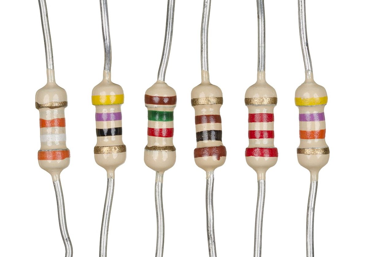
Why the bands follow a pattern
Resistor colour codes are not arbitrary. The common scheme, standardised in IEC 60062, uses the same ten colours for digits in the same order everywhere: black is 0, brown 1, red 2, orange 3, yellow 4, green 5, blue 6, violet 7, grey 8 and white 9. Once those ten are memorised, most of the decoding is simple arithmetic rather than memory.
The bands are read as a sequence. The first two bands are significant digits, the third band is a multiplier that says how many zeros follow those digits, and the last band is the tolerance. A five-band resistor adds a third digit before the multiplier. The multiplier colours follow the same ten-step ladder, with black as x1, brown x10, red x100, and so on, while gold and silver are fractional multipliers of 0.1 and 0.01 used for very low values.
Bench tip Memorise the first six colours in the digit order (black to blue) and the rest becomes much easier to recall under bench lighting.
Finding the starting end
The hardest part is often knowing which way to read. Tolerance bands are normally spaced a little further from the others, and gold or silver is the most common colour there. If you see a gold or silver band at one end, read from the opposite end. A resistor with no fourth band at all has 20 percent tolerance, and that can happen on older parts.
Be careful with body colour. Some resistors have a base colour that looks similar to a band, and a dark or faded band can look like black or brown. If the first band seems like it could be either the tolerance or a digit, reason out the value both ways and keep the one that matches a standard E-series value, such as 1.0 k, 2.2 k, 4.7 k or 10 k.
Bench tip Turn the resistor under a bright, neutral light and rotate it slowly; a magnifier helps on the smallest 0402-style parts.
A worked example
Take a four-band resistor with bands brown, black, red, gold. The gold band is at the right end and is spaced apart, so the reading goes left to right. Brown is 1, black is 0, giving the digits 10. Red is the multiplier x100. The arithmetic is 10 multiplied by 100, which equals 1000 ohms, or 1 k. Gold tolerance is 5 percent, so the part is 1 k plus or minus 50 ohms, meaning anything from about 950 to 1050 ohms is within specification.
Now a five-band example: red, violet, black, brown, brown. The last band is brown, which is 1 percent tolerance, and the first three bands give digits 2, 7 and 0, so the value is 270. The multiplier brown is x10, so 270 times 10 is 2700 ohms, or 2.7 k. A 1 percent tolerance on 2.7 k gives a window of roughly 2673 to 2727 ohms. A reading of 2.71 k on your meter is well inside that window.
Bench tip Write the decoded value on a sticky note or in your notes before measuring, so you compare against a target rather than guessing from the meter.
Checking with a multimeter
Measure resistance with the resistor out of circuit, or at least with the power off and one lead lifted, because parallel paths will pull the reading low. Set the meter to a range that brackets the expected value, so a 2.7 k part should sit on the 20 k range rather than the 200 ohm range. Touch the probes to the leads firmly and wait for the reading to settle before you write it down.
The meter tells you the actual value, and the bands tell you what the value should be. A reading that falls within the tolerance window is a good part. A reading far outside it, or one that drifts while you hold the probes, suggests a damaged or mislabelled part, or a poor contact in the probes or in the joint.
Bench tip If a reading is unstable, clean the lead ends with a little isopropyl alcohol or gently scrape them before blaming the part.