16 October 2026
Electrolytic vs Ceramic vs Film Capacitors: Picking the Right Dielectric
Electrolytic, ceramic, and film capacitors look interchangeable on a breadboard until they aren't. Here is how their dielectrics change capacitance, polarity, loss, and stability.
Why the Dielectric Matters on Your Bench
Two capacitors with the same label value can behave very differently in a circuit. The dielectric, the insulating material between the plates, sets how much capacitance you get per unit volume, how the value shifts with voltage, temperature, and frequency, how much energy is lost as heat, and whether the part has a polarity.
When you swap a part because the drawer is empty, you are really swapping those properties. A 100 nF capacitor in a filter, a timer, or a decoupling spot can work fine or drift badly depending on what it is made of.
Bench tip Before substituting, look at the dielectric code printed on the part or in its datasheet, not only the capacitance and voltage.
Electrolytic: Big Capacitance, Strict Rules
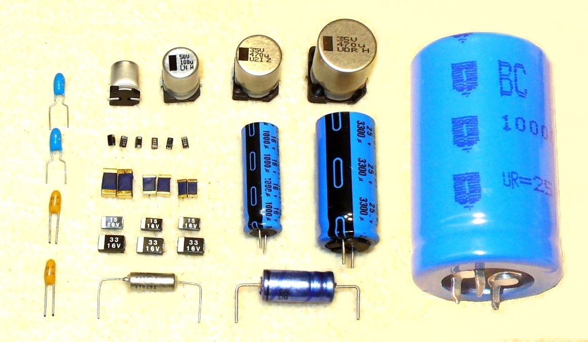
Aluminum and tantalum electrolytics use a very thin oxide layer as the dielectric, which allows large capacitance in a small can. Typical values run from about 1 µF to several thousand microfarads at voltages up to a few hundred volts. The oxide layer is formed under a specific polarity, so reversing a polarized electrolytic in a circuit can damage it, sometimes dramatically.
The trade-offs are real. Equivalent series resistance (ESR) is typically higher than in film or ceramic parts, rises as the electrolyte dries out with age, and increases in the cold. Tolerances are loose, often around plus or minus 20 percent. These parts are best for bulk storage, power supply smoothing, and low-frequency filtering.
Bench tip Keep the working voltage well above the circuit voltage, commonly with at least a 20 to 50 percent margin, because electrolytics are sensitive to overvoltage and heat.
Ceramic: Compact, Fast, and Sometimes Surprising
Multilayer ceramic capacitors pack many electrode layers into a small chip, giving low inductance and good high-frequency behavior. They are the default for decoupling and bypassing because they sit close to the circuit and respond quickly.
The catch is the dielectric class. Class 1 types such as C0G (NP0) are stable and low-loss but offer modest capacitance. Class 2 types such as X7R and Y5V give much more capacitance per volume, but their value can drop substantially under DC bias and temperature change, and some are also microphonic. A 10 µF part in an X5R or X7R case can measure well below its label once a few volts are applied across it, so check the datasheet's bias curve for critical uses.
Bench tip For timing, filters, or anything where the value must hold, prefer C0G or a film part over a high-K ceramic.
Film: Stable, Predictable, and Worth the Space
Film capacitors use a plastic dielectric such as polyester, polypropylene, or polystyrene with metal electrodes. They are non-polarized, have low dissipation, and hold their value well over time, temperature, and voltage. Their tolerance is typically tighter than electrolytic or high-K ceramic, often around plus or minus 1 to 5 percent in the better grades.
The downsides are size and cost for a given capacitance. Film parts are bulkier than ceramics and cannot match electrolytics for bulk values, but for audio coupling, active filters, and timing networks they are often the right choice.
Bench tip Polypropylene is generally a better low-loss choice than polyester for signal work, but both are fine for many hobby filters.
A Worked Example: RC Filter Cutoff
Suppose you build a simple RC low-pass filter with a 4.7 kΩ resistor and a 220 nF film capacitor. The cutoff frequency is f = 1 / (2πRC) = 1 / (2 × 3.1416 × 4700 Ω × 220 × 10⁻⁹ F). The product RC is about 1.03 × 10⁻³ seconds, so the denominator is about 6.50 × 10⁻³, giving f of roughly 154 Hz. A film part holds that value well, so the cutoff stays put.
Now imagine swapping in a 100 µF electrolytic for the same resistor, as if you wanted a slower filter. RC becomes 4700 × 100 × 10⁻⁶ = 0.47 seconds, and f is about 0.34 Hz. That is a time constant, not a filter, and an electrolytic's loose tolerance and ESR would make the result unpredictable. The same arithmetic shows why electrolytics belong in bulk supply roles and film or C0G parts in timing and filtering.
Bench tip Calculate RC before you choose the dielectric, and remember that real tolerances can move the cutoff by the sum of both parts' tolerances.