26 September 2026
How a Multimeter Actually Measures Resistance (and Where It Can Mislead You)
Your meter doesn't sense resistance directly—it injects a tiny current and measures a voltage. Knowing this explains most of the odd readings you get in-circuit.
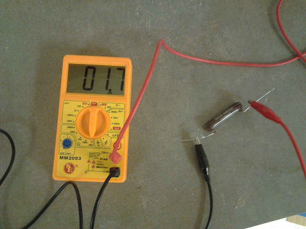
It's Really a Current Source in Disguise
When you flip a multimeter to its ohms setting, it doesn't passively 'read' resistance the way a ruler reads length. Instead, the meter pushes a small, known current through the component under test and measures the voltage that develops across it. Ohm's law then does the rest internally: resistance equals voltage divided by that known current, and the display just shows you the calculated result.
This is why a resistance measurement requires power from the meter itself, usually its internal battery, and why you should never measure resistance on a circuit that already has power applied. If an external voltage source is present, it fights with the meter's own current source and produces garbage readings, and in some cases can damage the meter's input circuitry.
Why It Has to Be Out of Circuit
The ohms function assumes the two probe points are connected only by the thing you're trying to measure. If that component is sitting on a breadboard or PCB with other parts wired in parallel with it, the meter's test current takes every available path, not just the one through your resistor. The reading you get is the parallel combination of everything connected between those two nodes, which is almost never what you intended to measure.
This is the single most common reason people think a good resistor is 'reading wrong.' A 10k resistor sitting next to a 10k resistor in parallel will measure close to 5k, and there's nothing wrong with either part. Lifting one leg out of the circuit, or at least out of the board entirely, is the only reliable way to get a trustworthy number.
Range Selection and the Low-End Trap
Most digital multimeters use different internal current levels depending on the resistance range selected, higher test currents for low-resistance ranges and lower currents for high-resistance ranges. This keeps the voltage developed across the component in a range the meter's front end can measure accurately, but it also means your own test lead resistance and contact resistance start to matter more as you measure smaller values.
On the lowest ohms range, a fraction of an ohm from lead resistance, oxidized probe tips, or a poor connection at the test points can visibly shift the reading. Some meters include a relative or zero function specifically so you can short the leads together first and subtract that baseline error, which is worth using whenever you're trying to measure something in the low single-digit ohms range, like a shunt resistor or a length of wire.
Diode-Like Components and Semiconductor Junctions
The ohms function assumes a linear, current-independent resistance, which is true for resistors but not for diodes, LEDs, or transistor junctions. Because the meter's test current is small and the voltage it produces across a PN junction doesn't scale linearly, an ohms reading on a diode is often meaningless or wildly inconsistent between meters. This is exactly why multimeters have a separate diode-test mode, which reports a forward voltage drop instead of a resistance value and is the correct tool for checking those parts.
If you ever get a strange, unstable, or clearly wrong ohms reading on something in circuit, it's worth asking whether a semiconductor junction elsewhere on the board is providing an alternate current path. Op-amp inputs, protection diodes, and even LEDs can quietly participate in a resistance measurement in ways that have nothing to do with the resistor you're actually trying to check.