4 November 2026
A Transistor's hFE: Why You Shouldn't Design Around One Exact Value
hFE varies widely between parts and with current, temperature, and age. Here is how to size a base resistor so your circuit works across the whole range.
Why hFE is a range, not a number
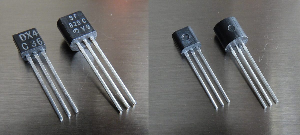
The current gain of a bipolar transistor, usually written hFE or beta, is the ratio of collector current to base current in the active region. Datasheets give a minimum, a typical value, and a maximum for a test condition, and in many small-signal NPN parts the spread between minimum and maximum is a factor of several. Two transistors from the same reel can differ noticeably, and the gain you measure on a curve tracer or a hFE socket on your multimeter describes only that one device at that one current and temperature.
Gain also moves with operating point. It typically peaks at a moderate collector current and falls off at very low currents and again as current climbs toward the upper end of the device's rating. Warming the die raises gain in many parts, so a transistor that tests fine cold may behave differently after a few minutes running. None of this is a defect; it is simply how the device behaves, and it is why a good design does not hinge on one value.
Bench tip Measure a handful of transistors from the same batch and note how far apart they are. That spread is a more honest picture than any single reading.
A worked example: driving a 20 mA load
Suppose you want an NPN transistor to switch a 20 mA load from a 5 V supply, and you want it fully on, meaning saturated, so its collector-emitter drop is small. Base-emitter voltage in conduction is roughly 0.7 V for a silicon part, so the resistor sees about 5 V minus 0.7 V, or 4.3 V. A common approach is forced beta: choose a base current that is a fixed fraction of the collector current, so the transistor saturates even when its gain is lower than you expected. If you pick a forced beta of 10, the base current target is 20 mA divided by 10, which is 2 mA. The base resistor is then 4.3 V divided by 2 mA, about 2.15 kilohms, so a 2.2 kilohm resistor gives roughly 1.95 mA of base drive.
Now compare a design that trusts a single gain value. If someone looks at a typical hFE of 100 and sizes the resistor to give exactly 20 mA at that gain, they need 0.2 mA of base current and a resistor near 21.5 kilohms. A 22 kilohm resistor delivers about 0.195 mA. With a real device whose gain at this current is only 30, the base current supports just 5.9 mA of collector current, which is not enough for the 20 mA load. The transistor leaves saturation, its collector sits well above its saturation voltage, and the load runs dim or unreliably. The circuit worked on the bench only because that particular transistor happened to be high-gain.
Bench tip Build the forced-beta version first and verify the collector voltage is near its saturation level with the load connected.
Choosing the margin
The forced beta you choose is a trade-off. A value near 10 is a common starting point for switching at these currents, since it keeps the transistor saturated across a wide range of real parts while keeping base current low enough that the driving logic or microcontroller pin is not overloaded. Much higher forced beta speeds turn-off and improves saturation margin, but it wastes base current and can slow switching when the base is driven hard and then has to be cleared. The right value depends on the speed you need, the current your driver can source, and how much temperature drift you expect.
Also check the base driver. A microcontroller output that provides a few milliamps may be fine for this example, but a logic pin with a low current limit cannot be relied on for higher loads, and a transistor in that situation may never fully saturate. If the load is large or inductive, a flyback diode and a suitable base or emitter arrangement may be necessary, but that is a separate concern from gain.
Bench tip If the load is a higher-current device than the transistor's rated continuous collector current allows, pick a bigger transistor rather than stretching the base resistor.
Testing your design across the spread
Once the circuit is built, do not stop at one transistor. Swap in a few parts of the same type and measure the collector-emitter voltage with the load on. If it stays low in every case, the design holds. If one part sits high, your base drive is too weak for that device, and the fix is a lower base resistor or a larger forced beta, not a search for a better-matched transistor.
When you are in doubt about the exact electrical limits for a particular part, read its datasheet and use the minimum and maximum values listed under the test conditions closest to your use. Where a number is not given, treat it as a typical range and design with margin.
Bench tip Keep a note of the collector voltage you measured with each transistor. It makes the next design decision faster.