1 November 2026
What a Flyback Diode Protects, and Why It Sits Across the Coil
A flyback diode across a relay or solenoid coil stops the large voltage spike that appears when the current is switched off. Here is how it works and how to size and place one.
Why a coil fights the switch
An inductor, whether it is a relay coil, a solenoid, or a motor winding, stores energy in its magnetic field. The voltage across it is proportional to how fast its current changes, so the relation is v = L times di/dt. While current is flowing steadily, the coil simply behaves like a resistor and the voltage across it is I times R. The trouble starts when you switch the current off.
If a transistor or relay contact opens in a few microseconds, the current wants to drop to zero almost instantly. The coil responds by generating whatever voltage is needed to keep the current going for a moment, and that voltage has the opposite polarity to the supply. The result is a brief spike that can easily exceed the voltage rating of the switch. This is the inductive kickback that flyback diodes exist to tame.
Where the diode goes and why it stays quiet
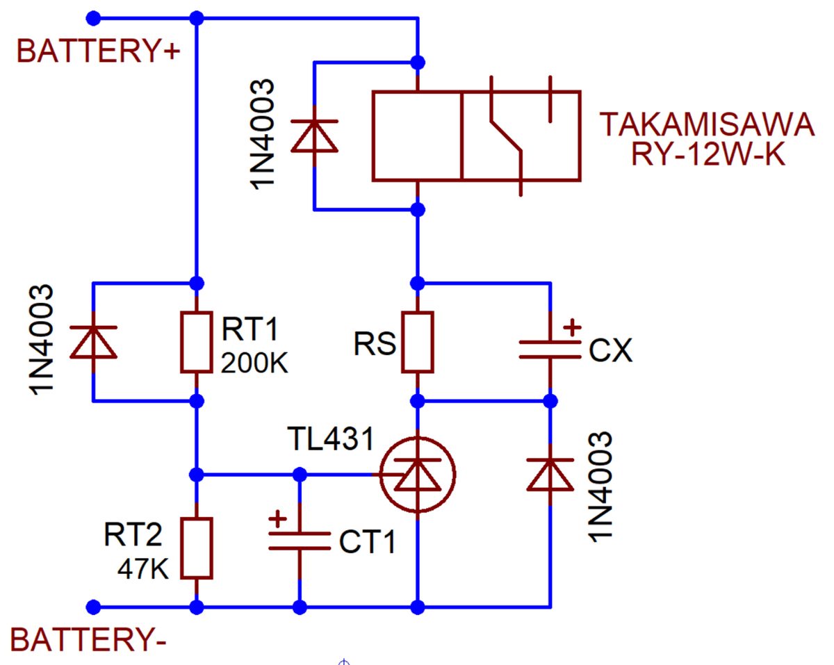
A flyback diode, also called a freewheeling or snubber diode in some contexts, is connected across the coil with its cathode toward the positive supply and its anode toward the switched end. During normal operation the supply holds the cathode positive, so the diode is reverse-biased and carries essentially no current. It only becomes active when the coil tries to reverse its voltage at turn-off.
When that happens, the coil's voltage forward-biases the diode and the reverse swing is clamped to roughly the supply voltage plus one diode forward drop, typically somewhere around 0.7 volts for a silicon rectifier. Instead of a path through the switch, the coil current now circulates through the diode and the coil's own resistance, decaying smoothly. The switch only sees the supply plus a small margin.
A worked example with a 12 V relay
Suppose a 12 V relay coil has a resistance of about 400 ohms and draws roughly 30 mA when energized. Assume the coil's inductance is around 0.5 henry, which is in the typical range for small relays, though you should measure or check the datasheet for a real design. The stored energy at turn-off is 0.5 times L times I squared, which is 0.5 times 0.5 times 0.03 squared, or about 0.23 millijoules.
Now consider the switch opening in 10 microseconds. The current change is 0.03 amps over 10e-6 seconds, so di/dt is 3000 amps per second. The inductive voltage is 0.5 times 3000, or 1500 volts. Real circuits have stray capacitance and wiring inductance that will alter the exact peak, but the order of magnitude is clear: without a clamp, a transistor rated for a few tens of volts would not survive.
With a flyback diode, the clamp holds the coil near 12.7 volts on the reverse swing. The decay time constant is L divided by R, which is 0.5 divided by 400, or 1.25 milliseconds. Current falls to near zero in roughly five time constants, so the coil releases in about 6 milliseconds rather than almost instantly. That slower release is the price of the protection.
Trade-offs and alternatives
The plain diode is the cheapest and most reliable choice, but it makes the coil release more slowly than it would with no clamp at all. For relays where release timing matters, a Zener diode in series with a second diode can clamp at a higher voltage, such as 2 to 3 times the supply, which gives a faster decay while still limiting the spike. A transient voltage suppressor, which is a Zener-like device designed for surges, can serve the same role.
A series resistor across the diode is another option, but it adds loss and does not clamp as tightly as a diode, so it is less common in simple designs. Whatever you choose, the protection device must be placed directly across the coil terminals, because any wire between the diode and the coil adds inductance and undermines the clamp.
Bench tips
Check polarity before power-up. A diode installed backward across a supply-driven coil will short the supply through the diode as soon as the drive is applied, which is often the first thing that goes wrong. Look for the band on the diode and confirm it sits toward the positive rail. A continuity or diode-test function on your multimeter will show the expected one-way conduction.
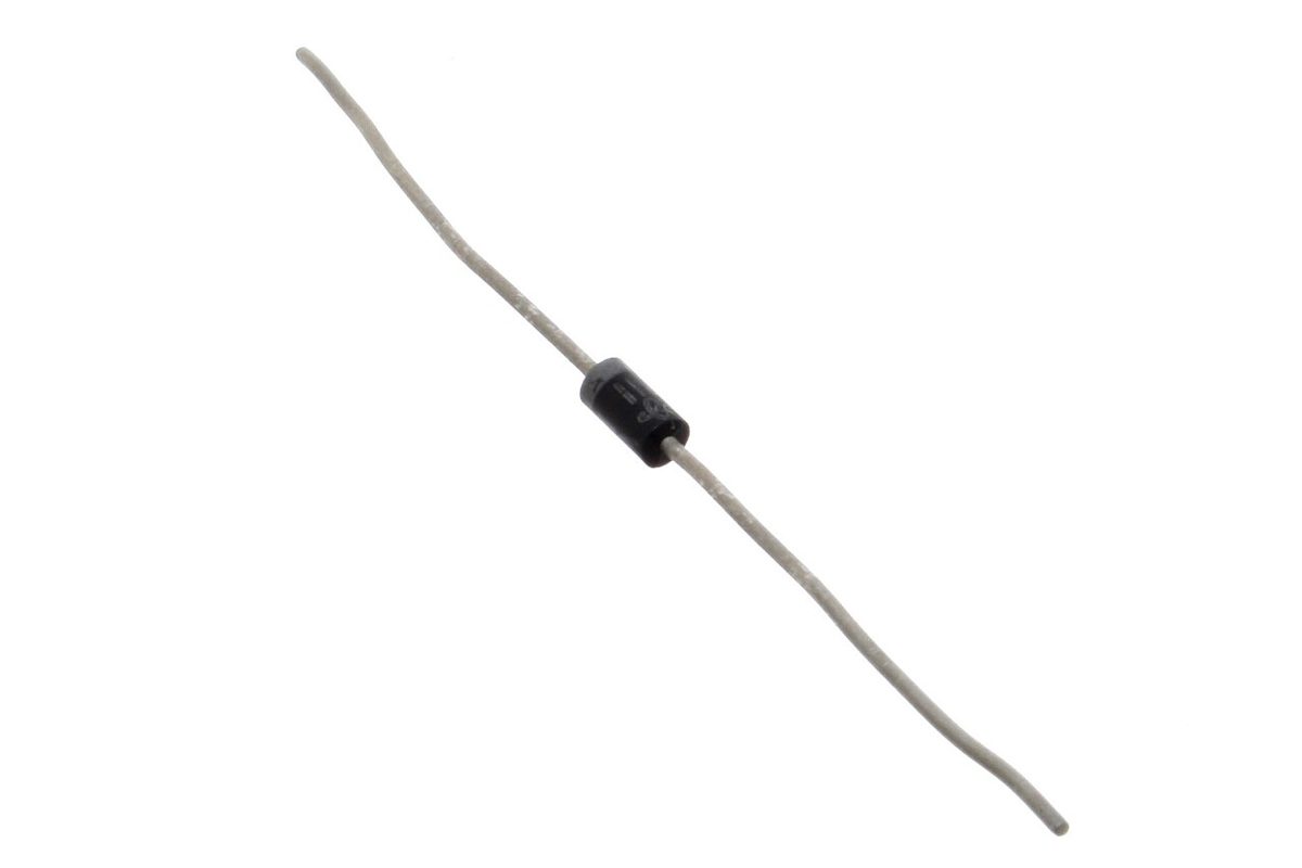
Choose a diode that handles the coil current with margin. General-purpose rectifier diodes in the 1N400x family are a common choice for small relays and solenoids. Keep the leads short, and if your transistor drives the coil low side, make sure the transistor's rated voltage is comfortably above the supply plus the clamp voltage.
Bench tip Measure the coil voltage with a scope or a fast probe when you switch it off. Seeing the spike flatten at the supply plus a diode drop is the quickest way to confirm the clamp works.