31 October 2026
BJT vs MOSFET as a Switch: Choosing the Right One at the Bench
A bench-focused comparison of how bipolar transistors and MOSFETs behave as switches, with a worked example driving a 100 mA load from a 3.3 V microcontroller pin.
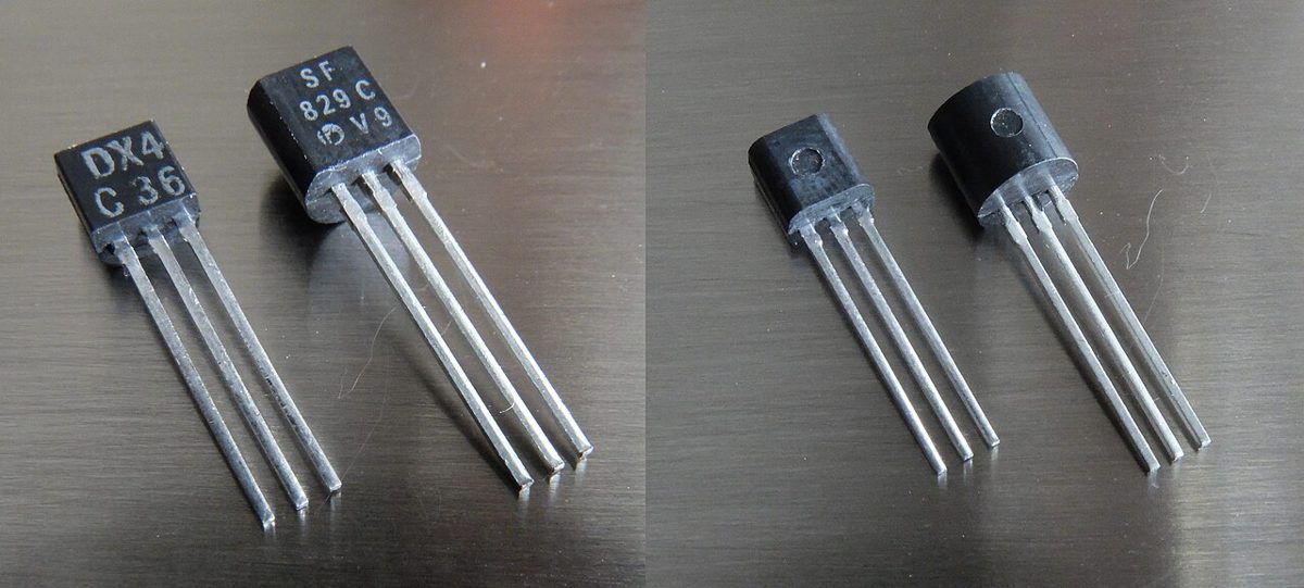
Why the Choice Matters on a Real Bench
Most hobby projects eventually need a microcontroller to switch something bigger than a pin can handle, such as a relay coil, a motor, an LED strip, or a heater element. Either a bipolar junction transistor or a MOSFET can do that job, and both will often work on the first try. The difference shows up when the circuit runs warm, when the logic voltage is low, or when the load is larger than you planned.
Picking the wrong type rarely causes an instant failure. More often you get a switch that barely turns on, a pin that runs hot, or a transistor that dissipates more than expected and needs a heatsink it did not need. Knowing how each device is driven saves that debugging.
How Each Device Is Driven
A BJT conducts when current flows into its base. The collector current it can pass is roughly the base current multiplied by the current gain, often specified as hFE. That gain varies a lot between parts and with current and temperature, so a sensible design does not rely on a single gain figure. Instead, you overdrive the base so the transistor saturates and the gain stops mattering much.
A MOSFET is controlled by the voltage on its gate, which is insulated from the channel by a thin oxide layer. Once the gate is charged, very little current flows, apart from brief charging spikes when switching. That is why a microcontroller pin can turn a MOSFET on and off directly. The catch is that the gate must be driven well above the device's threshold, and logic-level parts are specified for the voltages a 3.3 V or 5 V logic output can actually produce.
Worked Example: 100 mA Load from a 3.3 V Pin
Suppose you want to switch a 12 V load drawing 100 mA from a 3.3 V GPIO pin. For a BJT, assume the device saturates with a forced gain around 10, which is a conservative design choice. The base current needed is 100 mA divided by 10, or 10 mA. The base-emitter drop is typically around 0.7 V to 0.8 V, so the base resistor sees about 3.3 V minus 0.75 V, which is 2.55 V. Dividing by 10 mA gives roughly 255 ohms, so a 220 ohm resistor is a reasonable pick, giving about 11.6 mA of base drive. Check that your pin can source that much current, since many microcontroller pins have limits in the 10 mA to 25 mA range.
With a BJT at 100 mA, the saturation voltage is typically in the range of 0.1 V to 0.3 V. Power in the transistor is about 0.2 V times 0.1 A, or 20 mW. The base drive itself dissipates roughly 0.75 V times 11.6 mA, about 9 mW, which comes from the logic pin rather than the load supply.
For a logic-level MOSFET, the gate draws almost nothing at steady state, so a series gate resistor of around 100 ohms and a pull-down resistor of around 10 k ohms to ground are enough to make the switch behave. The on-resistance of many logic-level parts is in the tens of milliohms at this current. Even at 0.05 ohm, the conduction loss is 0.1 A squared times 0.05 ohm, or 0.5 mW. Confirm the on-resistance at the gate voltage you actually apply, since datasheets often list it at 4.5 V or 10 V.
Bench tip Check the gate threshold and Rds(on) curves at 3.3 V before trusting a MOSFET with a microcontroller pin, because some parts only turn fully on at higher gate voltages.
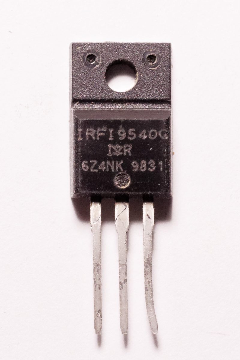
When to Pick Each One
Choose a MOSFET when the load is moderate to large, when you want little heat in the switch, or when the drive pin is limited in current. Logic-level N-channel MOSFETs with the source tied to ground and the load on the high side of the drain are the usual starting point for low-side switching. P-channel parts are convenient for high-side switching with the gate pulled low, though they are often more expensive per amp of capability.
Choose a BJT for small, low-stakes switching where its simplicity is an advantage, or where the circuit already has spare base current available. A BJT is also a fine choice when you need a predictable saturation voltage rather than a value that depends on gate drive. Either way, verify the switch with a multimeter: measure the voltage across the switch when it is on and confirm it is close to the saturation or on-resistance drop you expected.
Bench tip Measure the drain-to-source or collector-to-emitter voltage with the load running. If it is more than a few tenths of a volt, the switch is not fully on.