25 September 2026
Ohm's Law in Practice: Reading a Resistor Under Real-World Tolerances
Ohm's Law gives you a clean prediction, but real resistors and meters wander from the ideal. Here's how to account for tolerance without second-guessing your bench work.
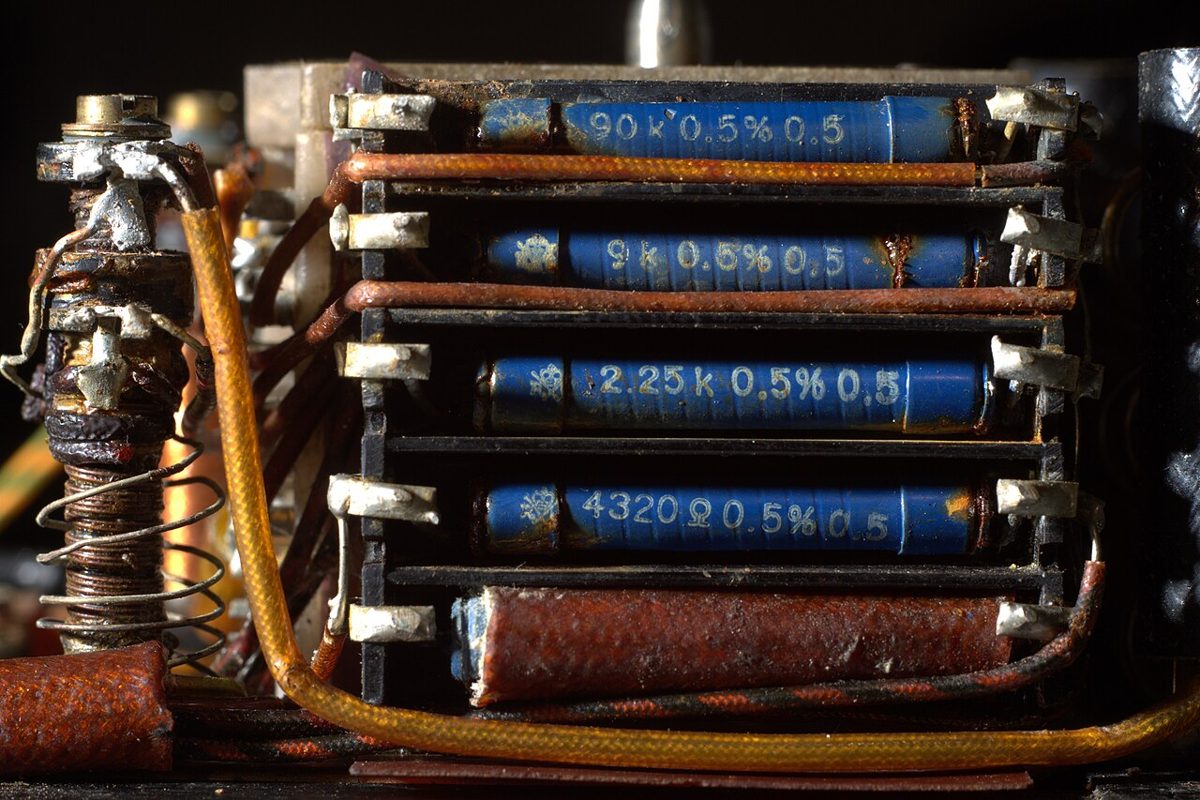
The law is exact, the parts aren't
V = IR is a mathematical relationship, not a promise about any specific component. A resistor's printed or coded value is a target the manufacturer aimed for, and the tolerance band is how far off the actual part is allowed to land while still being sold under that label. A 1kΩ resistor with 5% tolerance can legitimately measure anywhere from about 950Ω to 1050Ω straight out of the bag, and that's before temperature, aging, or measurement error enter the picture.
This matters the moment you start predicting currents or voltage drops. If you calculate an LED current-limiting resistor assuming a perfect 330Ω and the real part is 5% high, your current is a few percent lower than planned - usually harmless for an LED, but the same margin can matter a lot more in a precision reference or a timing circuit.
What the color bands (or printed code) actually tell you
Common tolerance classes you'll encounter on hobbyist-grade resistors are 5% (gold band), 2% (red band, less common), and 1% (brown band, typical for metal-film resistors). Precision resistors can go tighter, down to fractions of a percent, but those are specialty parts, not what you pull from a generic assortment kit.
The tolerance band tells you the guaranteed worst case at the time of manufacture, at a reference temperature - it says nothing about how the part behaves as it heats up on your board or ages over years. A carbon-film 5% resistor and a metal-film 1% resistor can drift differently under heat even if they started at the same measured value, so tolerance alone isn't the whole story for demanding designs.
Measuring instead of trusting the code
Before you rely on a resistor in a calculation-sensitive spot, it's worth measuring it with your multimeter rather than trusting the bands. This does two things: it confirms you read the color code correctly (easy to flip on faded or oddly-lit bands), and it gives you the actual value to plug into Ohm's Law instead of the nominal one.
Keep in mind your meter has its own uncertainty, typically a percent or so on resistance ranges for a decent handheld unit, plus a count or two of digit resolution. For everyday work this is negligible, but if you're chasing a tight current target, remember you're stacking the resistor's tolerance with the meter's own error - don't treat a four-digit readout as four digits of truth.
Designing with margin instead of exact numbers
The practical habit is to design for a range, not a point value. When sizing a current-limiting or pull-up resistor, calculate the current or voltage at both ends of the tolerance band and check that your circuit still behaves acceptably at the worst case, not just the nominal one. For LEDs this usually means checking you're not exceeding the maximum current at the low-resistance extreme.
If a circuit truly can't tolerate a few percent of drift - a voltage reference divider or a precision timing network, for example - that's the signal to reach for 1% or tighter parts and budget extra time to measure and possibly hand-select resistors rather than trusting any single one out of the bin. For most hobby work, though, understanding that your calculated numbers are centers of a range, not guarantees, is enough to keep Ohm's Law predictions and bench measurements from seeming to disagree.