حاسبة مجانية على الإنترنت
حاسبة تشغيل بوابة MOSFET
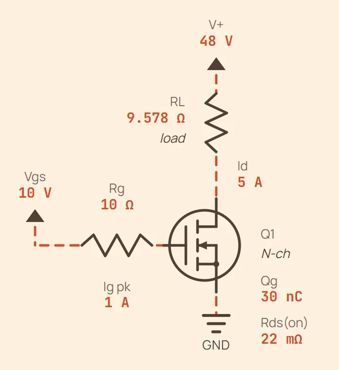
مثال The driver must source 1 A at the start of each edge, and tr + tf = 60 ns (estimated from Qg and Rg) — gate drive power 30 mW, which the driver and Rg burn, not Q1.
مثال Q1 itself dissipates 995 mW = 720 mW switching + 275 mW conduction (72.36% of it is the edges); 1.025 W once the gate drive is counted too. Rg is the knob between the two failure modes: more of it damps the gate loop but stretches the edges — at 20 Ω the switching loss doubles to 1.44 W — and less of it doubles the drain's dV/dt and lets the gate ring against the loop inductance — at 5 Ω it halves to 360 mW. Conduction is the temperature-sensitive half: Rds(on) is roughly 1.5× higher at 100 °C, so budget 412.5 mW for it.
المعادلة
بالقيم الافتراضية
A MOSFET draws no steady gate current, so holding it on is free — but every edge has to shovel the whole gate charge in and back out again, and is real power out of the driver's supply. The mistake is then treating the gate resistor as free too: it is the only damping in the gate loop, and it is also what stretches the edges that the switching loss is directly proportional to — — while the part only earns its keep conducting, at .
With no measured edge times, the estimate comes from the gate loop itself: the driver starts at Ig = Vdrive/Rg and sags towards zero as the gate fills, so it averages about half of that, and moving Qg at that average takes . It is a first-order figure — the real Miller plateau is what sets the drain's transition — so put your datasheet's or your scope's numbers into the optional field whenever you have them.
ما تُدخله
- Total gate charge Qg
- Gate drive voltage (V)
- Gate resistor Rg (Ω)
- Switching frequency (Hz)
- Drain current Id (A)
- Off-state Vds (V)
- Rds(on)
- Duty cycle (%)
- Measured tr + tf (optional)