Diagrama de pines
Pines de Conector de ventilador de PC (PWM de 4 pines, Intel 4 hilos)
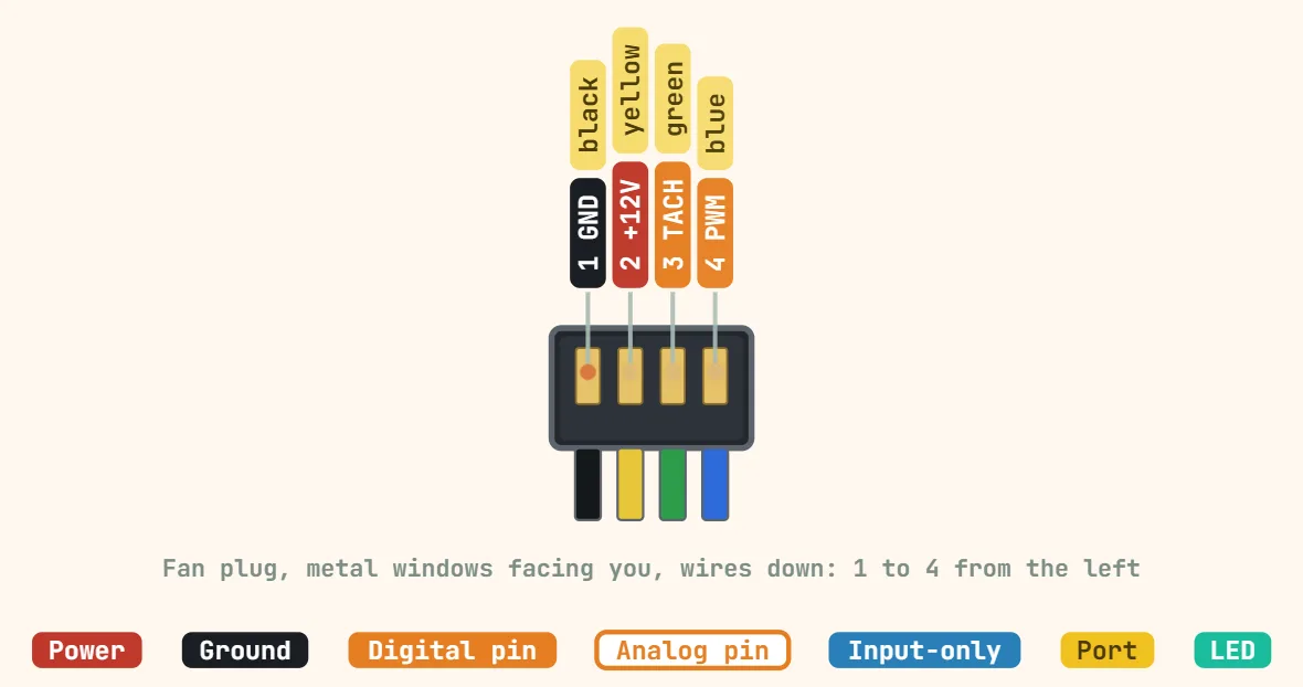
Pines
- 1: GND (black) — fan ground and the return path for the tach signal
- 2: +12V (yellow) — sits at full 12V on a 4-pin header; the fan regulates its own speed from the PWM line, so never try to slow a 4-wire fan by lowering this rail
- 3: TACH / SENSE (green) — open-collector output from the fan, 2 pulses per revolution, so RPM = pulses per second × 30. It needs a pull-up to 5V or 3.3V (the motherboard has one, an MCU does not) and it only pulls low, so it will never over-volt a 3.3V input through a 3.3V pull-up
- 4: PWM CONTROL (blue) — 25kHz control input (21–28kHz per spec), 5V logic, pulled up inside the fan and rated to sink about 5mA, so drive it open-drain from a 3.3V MCU rather than pushing 3.3V high. A 3-pin fan simply has no pin 4: it plugs onto pins 1–3 of the same header (the plug is keyed and offset) and is then speed-controlled by varying its 12V rail in DC mode instead. Conversely a 4-pin fan on a 3-pin header runs flat out, because its PWM line floats to its internal pull-up
Especificaciones
| Contactos | 4 |
|---|---|
| Paso | 2.54 mm |
| Alimentación | 12 V |
| Frecuencia PWM | 25 kHz (21–28 kHz) |
| Entrada PWM | 5 V máx., drenador abierto, absorbe ≈ 5 mA |
| Tacómetro | Colector abierto, 2 pulsos por vuelta |
| RPM | Pulsos por segundo × 30 |
| Ventiladores de 3 pines | Encajan en los pines 1–3, velocidad fijada por la tensión de alimentación |
Notas
- Sujeta el conector del ventilador con sus ventanas metálicas hacia ti y los cables hacia abajo: el pin 1 (negro, GND) está a la izquierda. En el cabezal de la placa base, visto desde arriba con su pestaña de plástico detrás, los mismos pines se leen 4-3-2-1 de izquierda a derecha.