Diagrama de pines
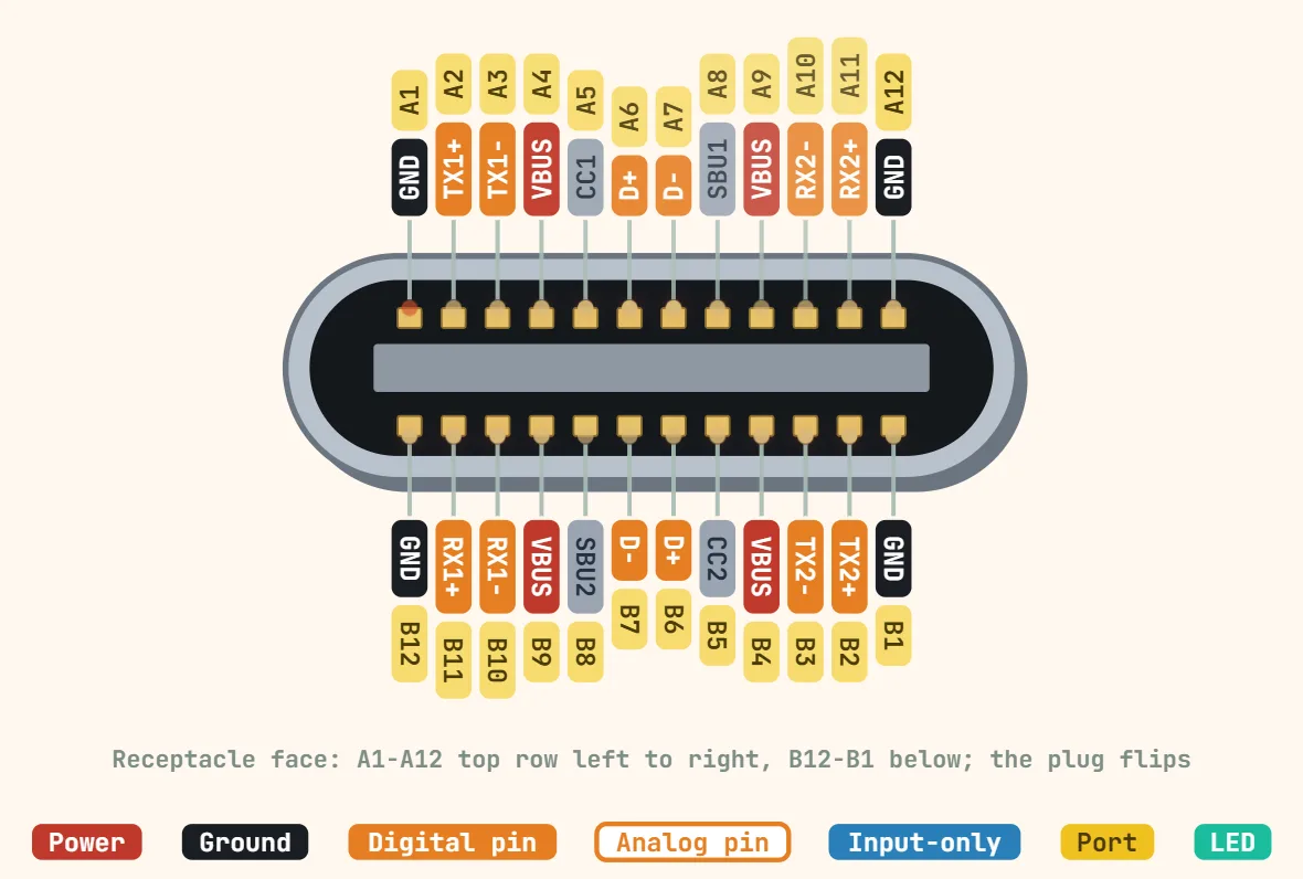
Pines de USB Type-C (receptáculo compatible con USB-PD)
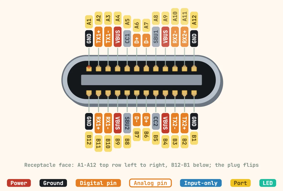
Pines
- A4/B4, A9/B9 — VBUS: four pins tied to one net, not four separate rails, so the current is split across more contact area; sits at a fixed 5V by default and only rises once a PD contract is actually negotiated over CC.
- A1/B1, A12/B12 — GND: the return path for VBUS and for both SuperSpeed pairs, likewise duplicated across four pins for current capacity, not wired as separate grounds.
- A5 — CC1, B5 — CC2: only whichever pin actually mates carries the Configuration Channel (the other is left floating or becomes VCONN — see below). Its DC level, set by an Rd/Rp resistor pair, is how the two ends first sense that something is even plugged in and which side is the power source, before any data moves.
- That same mated CC pin then carries the actual USB-PD protocol: Biphase Mark Coded (BMC) messages at a nominal 300 kb/s (±10%), built from a preamble, a message header, a data payload and a CRC — a real serial link, not a DC level, so a multimeter on CC only ever shows the idle Rp/Rd voltage and never the negotiation traffic.
- The CC pin that did NOT mate becomes VCONN whenever a cable needs it — an electronically-marked ("e-marked") cable, any USB 3.x/4 cable, or any link sourcing over 3A: the source or sink switches roughly 5V onto it, spec’d at a minimum of 1W (about 200mA) to run the cable’s ID chip and any signal redrivers inside it.
- A6/A7 and B6/B7 — two mirrored USB 2.0 D+/D− pairs; only one pair is actually driven per insertion, selected by which CC line mated. The second pair exists purely so the plug works either way up, not to add bandwidth.
- A2/A3+A10/A11 and B2/B3+B10/B11 — SSTX/SSRX SuperSpeed differential pairs (USB 3.x); same reasoning as D+/D−, only one full A-side or B-side set is live per orientation.
- A8/B8 — SBU1/SBU2: idle on plain USB and on PD itself, these are handed to an Alt Mode’s sideband channel (e.g. DisplayPort’s AUX line) once a Vendor-Defined Message negotiated over CC puts the port into that mode.
Especificaciones
| Contactos | 24 (receptáculo) |
|---|---|
| VBUS por defecto | 5 V hasta que se negocia un contrato PD |
| Tensiones fijas PD (SPR) | 5, 9, 15, 20 V |
| Tensiones fijas PD (EPR, PD 3.1) | 28, 36, 48 V |
| Corriente máxima | 3 A; 5 A con un cable e-marked de 5 A |
| Potencia máxima | 100 W (SPR, 20 V × 5 A), 240 W (EPR, 48 V × 5 A) |
| PPS (PD 3.0) | 3.3–21 V en pasos de 20 mV |
| Negociación | BMC en CC, 300 kbit/s |
| VCONN | 5 V, al menos 1 W, para cables e-marked |
| Circuitos integrados trigger de receptor | STUSB4500, CH224, IP2721, FUSB302 |
Notas
- Una conexión USB-C sin más solo garantiza 5V. Cualquier escalón superior del "Standard Power Range" (9V, 15V, 20V, y 12V en algunos cargadores) y cualquier escalón del "Extended Power Range" añadido en PD 3.1 (28V, 36V, 48V, hasta 5A/240W) es algo que el receptor debe pedir explícitamente y la fuente concederlo por el protocolo de datos de CC — no hay ningún truco de resistencias que dé 9V o más, como sí logran sin PD real algunos sistemas propietarios de carga rápida.
- Un dispositivo que solo baja CC con una Rd fija de 5.1 kΩ, sin lógica PD detrás, sigue recibiendo alimentación (esto es "USB Type-C Current" simple, limitado a 5V/3A ≈15W según el pull-up que eligió la fuente) — pero nunca verá nada por encima de 5V, porque no hay nada que realice el intercambio BMC.
- Para sacar más de 5V de un cargador PD sin escribir tu propia pila USB-PD, usa un CI receptor/trigger PD dedicado que haga la negociación CC por ti (p. ej. STUSB4500, CH224, IP2721, FUSB302) y ofrezca una interfaz sencilla por pines de configuración o I2C para pedir una tensión fija cuando indique que hay un contrato establecido.
- Una fuente solo ofrece los PDO que realmente implementa — un cargador básico de 5W/10W puede quedarse en 5V o 9V, mientras que un cargador de portátil puede llegar a 20V o, en los cargadores EPR más nuevos, a 48V — así que comprueba sus Source_Capabilities anunciadas en lugar de suponer que todo "cargador PD" alcanza todas las tensiones.
- Que VBUS y GND estén repartidos en cuatro pines cada uno es una medida de capacidad de corriente y resistencia de contacto, no cuatro redes independientes — por ejemplo, no trates el VBUS de A9 como conmutable por separado del de A4.