Brochage
Brochage Amplificateur de puissance audio LM386
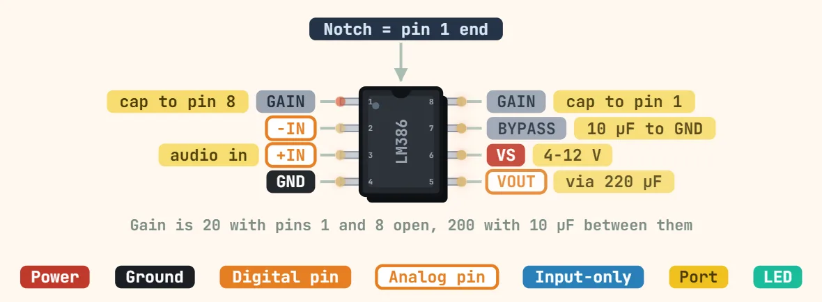
Broches
- 1: GAIN — one end of the internal gain-setting network shared with pin 8; left open, an internal 1.35kΩ resistor sets the default voltage gain to 20 (26dB).
- 2: −IN (inverting input) — audio signal input, roughly 50kΩ input resistance; AC-couple the source here since a DC path would drag on the input bias current.
- 3: +IN (non-inverting input) — the input normally used for a single-ended mic/line signal through a coupling capacitor, with pin 2 tied to ground for a simple mono circuit.
- 4: GND — ground reference for the chip and the return path for the input signal; keep this trace short and shared with the supply decoupling cap's ground to avoid injected hum.
- 5: VOUT — audio output, biased at roughly Vs/2 at idle; always drive the speaker through a series coupling capacitor (typically 220–250µF for a small 8Ω speaker) to keep that DC bias out of the voice coil.
- 6: VS — positive supply, about 4–12V typical for the common -N1/-N3 grades (some -N4 parts allow more — check the exact suffix); needs a local decoupling capacitor right at the pin or the amp can motorboat.
- 7: BYPASS — taps the internal half-supply reference; bridging it to ground with roughly a 10µF capacitor improves power-supply ripple rejection and cuts hum, especially at the higher gain setting.
- 8: GAIN — the other end of the gain network (see pin 1); bridging pins 1 and 8 with a capacitor removes that internal 1.35kΩ resistor and raises gain to about 200 (46dB), or add a resistor in series with the cap for anything in between.
Caractéristiques
| Tension d'alimentation | LM386N-1/-3: 4–12 V; LM386N-4: 5–18 V |
|---|---|
| Quiescent current | ≈ 4 mA typ at 6 V |
| Output power | N-1: 325 mW (6 V, 8 Ω); N-3: 700 mW (9 V, 8 Ω); N-4: 1 W (16 V, 32 Ω) |
| Voltage gain | 20 (pins 1–8 open) up to 200 (capacitor across pins 1–8) |
| Bande passante | ≈ 300 kHz (6 V, gain 20) |
| Input resistance | ≈ 50 kΩ |
| Distortion | ≈ 0.2% THD typ |
| Output idle level | ≈ VS/2 — use a coupling capacitor to the speaker |
| Boîtier | DIP-8, SOIC-8 |
Notes
- The VS pin (6) needs a real decoupling capacitor right at the package — commonly a 0.1µF ceramic plus a 100µF+ electrolytic — because at the LM386's higher gain settings a poorly decoupled supply rail is a well-known cause of low-frequency 'motorboating' oscillation.
- VOUT (pin 5) idles at about half the supply, so wiring a speaker straight to it without a series coupling capacitor (typically 220–250µF into a small 8Ω speaker) passes DC through the voice coil instead of just audio.
- Gain does not scale smoothly with just any resistor between pins 1 and 8: leaving them open gives about 20x, a capacitor alone across them gives about 200x, and anything in between needs a resistor placed in series with that capacitor.
- Supply range and rated output power vary by exact part suffix — a common LM386N-1/N-3 has a recommended operating range of about 4–12V (absolute maximum 15V) and delivers roughly 325mW into 8Ω at 6V, while an LM386N-4 is rated for a higher supply, about 5–18V recommended (absolute maximum 22V) — so check the datasheet for the specific grade in hand rather than assuming one number covers every LM386.