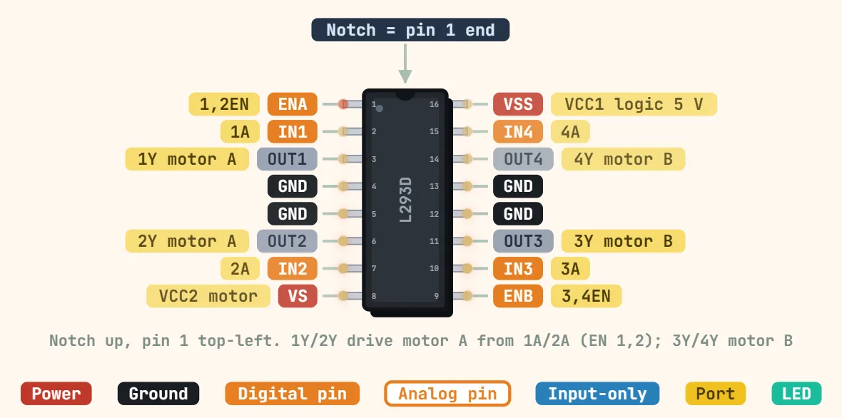
1: ENA (1,2EN) — enable motor A; PWM here for speed
2: IN1 (1A) — motor A direction input
3: OUT1 (1Y) — motor A output
4, 5: GND — also the heat path: the four centre pins carry the die heat into the PCB copper
6: OUT2 (2Y) — motor A output
7: IN2 (2A) — motor A direction input
8: VS (VCC2) — motor supply, 4.5–36V
9: ENB (3,4EN) — enable motor B
10: IN3 (3A) — motor B direction input
11: OUT3 (3Y) — motor B output
12, 13: GND
14: OUT4 (4Y) — motor B output
15: IN4 (4A) — motor B direction input
16: VSS (VCC1) — logic supply, 5V
विनिर्देश
Logic supply (VCC1)
4.5–7 V (5 V typical)
Motor supply (VCC2)
VCC1 – 36 V
Output current
600 mA per channel continuous
Peak output current
1.2 A per channel (non-repetitive)
Logic input HIGH
≥ 2.3 V
Outputs
4 half-H drivers (2 full bridges)
Flyback diodes
Built in (L293D only)
Switching frequency
5 kHz
Protection
Thermal shutdown
पैकेज
DIP-16
नोट्स
IN1/IN2 HIGH/LOW pairs set the direction of motor A (both the same = brake); ~600mA continuous per channel, 1.2A peak, and about 2V dropped across the bridge at full load.
The L293D variant has flyback diodes built in; the plain L293 does not — check which one you have before driving inductive loads.