Brochage
Brochage Module RTC DS1307
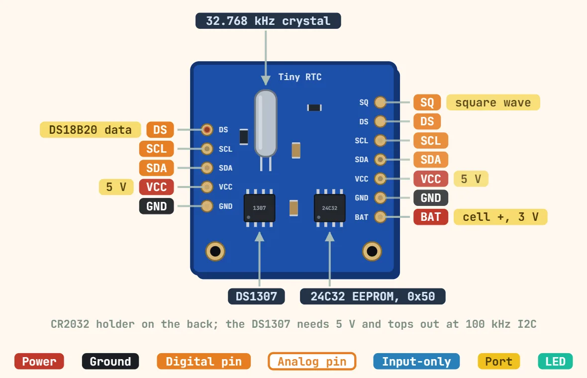
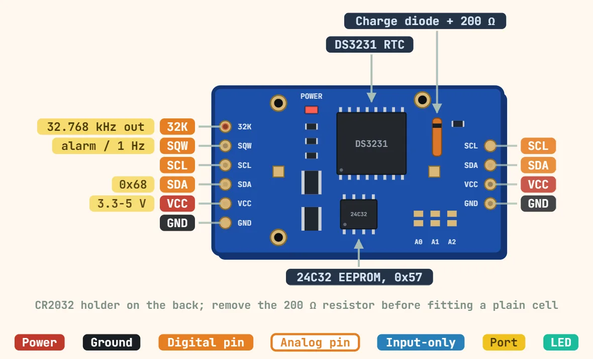
Broches
- SQ — the DS1307's SQW/OUT pin: open-drain square-wave / interrupt output, programmable to 1Hz, 4.096kHz, 8.192kHz or 32.768kHz, or a fixed high/low level; it needs its own external pull-up to be usable and is left floating (and useless as an interrupt) without one.
- DS — data pin of the optional DS18B20 temperature sensor (the unpopulated U1 footprint on the board); it carries nothing unless that sensor is fitted.
- SCL — I2C clock line; the DS1307 only supports standard-mode I2C up to 100kHz, not the 400kHz fast-mode some newer RTC chips (including the DS3231) support.
- SDA — I2C data line, open-drain; most of these breakout boards already carry their own pull-up resistors to VCC, so external ones usually aren't needed.
- VCC — main 5V supply; the DS1307 is a true 5V part (4.5–5.5V per the datasheet, no 3.3V mode), so feeding it 3.3V from an ESP32 or similar leaves it out of spec even though the I2C lines may look like they're toggling.
- GND — common ground, shared by the RTC itself, the SDA/SCL pull-up resistors, and the onboard AT24C32 EEPROM.
- BAT — the backup cell's positive terminal brought out to a pin, for watching its voltage with an ADC; it is not a supply input.
- The second, 5-pin header on the opposite edge repeats DS, SCL, SDA, VCC and GND, so another I2C board can be chained from it.
- Onboard CR2032 backup battery (3V coin cell) — keeps the clock and its small battery-backed RAM running through a power loss; many of these boards include a small trickle-charge resistor meant for rechargeable cells, worth checking before leaving a standard non-rechargeable CR2032 installed long-term.
- Onboard AT24C32 EEPROM — a separate 32Kbit I2C EEPROM chip on the same SDA/SCL lines as the RTC but at its own fixed address (0x50 by default), independent of the DS1307's own address (0x68).
Caractéristiques
| Tension d'alimentation | 4.5–5.5 V |
|---|---|
| Backup battery | 2.0–3.5 V (CR2032 on most modules) |
| Battery current | ≈ 500 nA typ with oscillator running |
| Interface | I2C, 100 kHz only |
| I2C address | 0x68 (RTC); 0x50 for the AT24C32 EEPROM on most modules |
| Quartz | External 32.768 kHz, 12.5 pF load |
| Accuracy | Depends on crystal and temperature (no compensation) |
| Battery-backed RAM | 56 bytes |
| SQW output | 1 Hz, 4.096, 8.192 or 32.768 kHz, open-drain |
| Operating temperature | DS1307: 0–70 °C; DS1307N: −40–85 °C |
Notes
- The DS1307 needs a genuine 5V supply to work correctly (its oscillator drive and register writes are out of spec below roughly 4.5V) — unlike the DS3231 modules it's often confused with, there is no 3.3V-tolerant version, so it is not a drop-in part for a 3.3V-only board like most ESP32 or STM32 designs without level shifting.
- It has no internal temperature compensation, so accuracy depends entirely on the external 32.768kHz crystal and its load capacitors, and it drifts noticeably more with temperature than a DS3231 — a typical hobby-grade module is on the order of a few minutes of drift per month, versus roughly a couple of minutes a year for a DS3231.
- A DS1307 that appears completely 'dead' (not counting at all) usually just has its Clock Halt (CH) bit set in the seconds register — this happens on first power-up or after the backup battery runs fully down, and most RTC libraries clear it automatically the first time you write the current time, so check the library's init call before assuming a bad chip.
- SDA and SCL are shared with the onboard AT24C32 EEPROM that ships on almost every DS1307 breakout, so an I2C bus scan correctly shows two devices — 0x68 for the RTC and 0x50 for the EEPROM — rather than one; that is expected, not a wiring fault.