Brochage
Brochage Pilote de ligne RS-232 MAX232 (DIP-16)
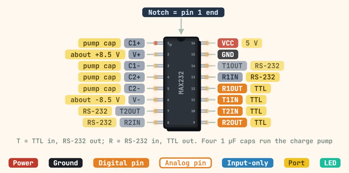
Broches
- 1: C1+
- 2: V+
- 3: C1−
- 4: C2+
- 5: C2−
- 6: V−
- 7: T2OUT
- 8: R2IN
- 9: R2OUT
- 10: T2IN
- 11: T1IN
- 12: R1OUT
- 13: R1IN
- 14: T1OUT
- 15: GND
- 16: VCC
Caractéristiques
| Tension d'alimentation | 4.5–5.5 V (single 5 V supply) |
|---|---|
| Supply current | ≈ 8 mA typ (no load) |
| Channels | 2 drivers + 2 receivers |
| Driver output swing | ≈ ±7 V typ into 3 kΩ (±5 V min) |
| Receiver input range | ±30 V |
| Débit | Up to 120 kbit/s |
| Charge-pump capacitors | 4 × 1 µF (MAX232); 0.1 µF on the MAX232A |
| Logic side | TTL/CMOS 5 V levels |
| Operating temperature | MAX232C: 0–70 °C; MAX232I: −40–85 °C |
| Boîtier | DIP-16, SOIC-16 |
Notes
- This is the chip the RS-232 entry above recommends by name for a level shift. Runs from a single 4.5–5.5V rail — it generates its own ±~9V RS-232 swing internally, from that one supply, through a charge-pump doubler/inverter that needs 4 external capacitors on C1+/C1−/C2+/C2− (1µF each is the datasheet's own reference design).
- Two independent channels, and it is easy to cross them by accident when wiring: Driver/receiver 1 is T1IN(11)→T1OUT(14) going out to RS-232, and R1IN(13)→R1OUT(12) coming back from it. Channel 2 is the same shape at T2IN(10)/T2OUT(7) and R2IN(8)/R2OUT(9). A µC's TX goes to a TxIN pin, its RX comes from the matching RxOUT pin — never wire a µC directly to a Tx*OUT or Rx*IN, those already expect RS-232 levels.