Brochage
Brochage Module capteur à effet Hall (KY-003, A3144, 3 broches)
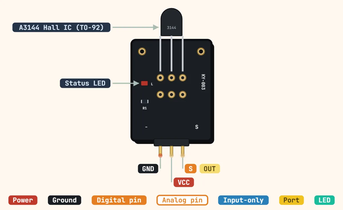
Broches
- GND — the pin marked "−"
- VCC — the pin marked "+": power for the onboard Hall IC (commonly rated 4.5–24V on the bare chip; see notes on 3.3V rails)
- S — signal, the pin marked "S": open-collector digital output, pulls LOW when a magnet's trigger pole gets close enough, released back HIGH by a pull-up once it moves away
Caractéristiques
| Sensor IC | A3144 unipolar Hall-effect switch |
|---|---|
| Tension d'alimentation | 4.5–24 V (A3144 rating; 5 V typical) |
| Supply current | ≈4.4 mA typical (chip) |
| Sortie | Open-collector, active LOW near a magnet |
| Output sink current | 25 mA max |
| Output saturation | ≤ 0.4 V at 20 mA |
| Magnetic response | Unipolar, non-latching: one pole only (south facing the marked face) |
| Onboard parts | Pull-up resistor + indicator LED |
Notes
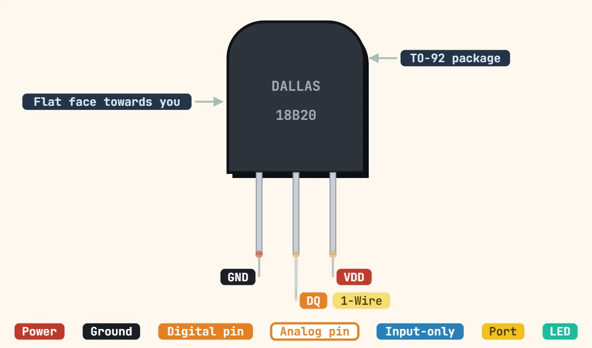
- This entry is the small 3-pin breakout board (the KY-003 layout), not the bare TO-92 A3144 chip by itself (see the DS18B20 entry above for what a bare TO-92 part looks like) — the board adds the resistor and status LED the bare chip needs to give a clean digital signal.
- The A3144 itself is specified for a 4.5–24V supply, not down to 3.3V — a module wired straight to a 3.3V logic rail (common on ESP32/RP2040 boards) can read as permanently HIGH or trigger unreliably even though OUT itself is a perfectly fine 3.3V-compatible signal once the chip is actually powered enough to switch.
- Unipolar and non-latching: it reacts to only one pole of a magnet, not both, and releases on its own as the field weakens — unlike a bipolar Hall latch, which needs the opposite pole to reset. If holding a magnet to the sensor does nothing, flip the magnet over before assuming the module is faulty.
- OUT is an open-collector transistor, typically rated to sink on the order of 20–25mA — enough to drive an LED or a microcontroller input directly, not a relay coil or motor without a driver transistor in between.