Pinagem
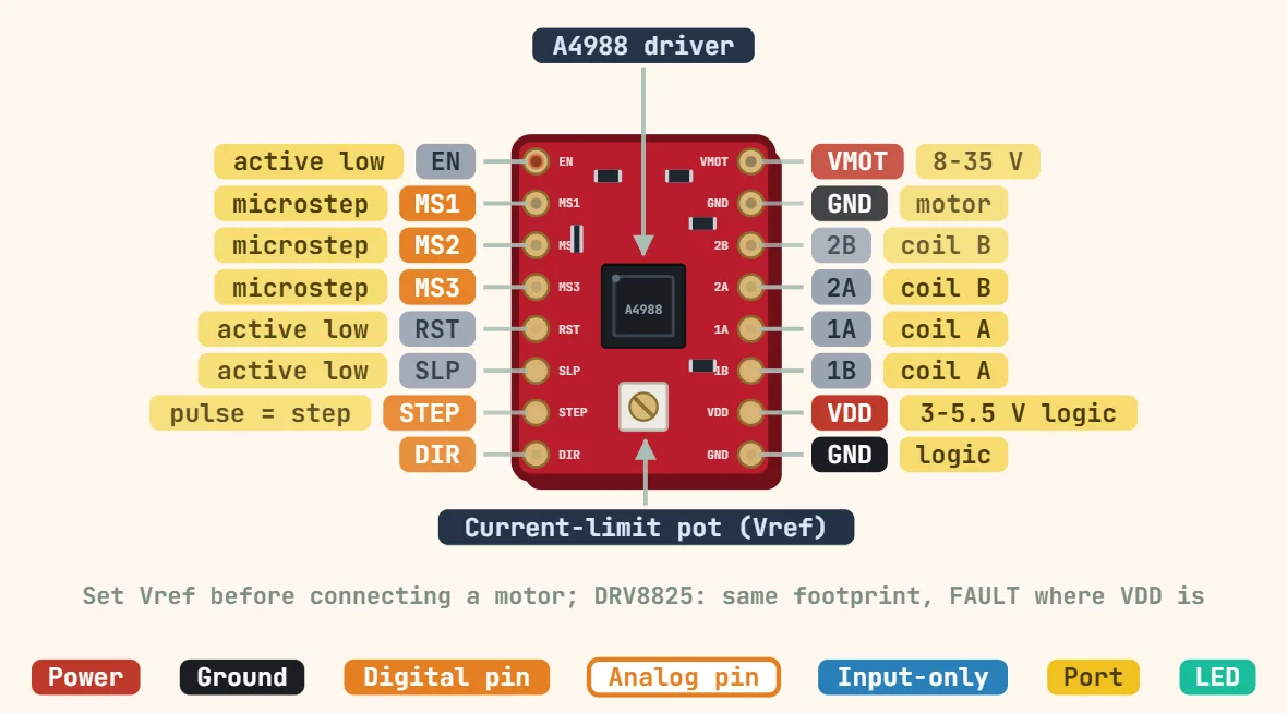
Pinagem Driver de motor de passo DRV8825 (placa StepStick / Pololu)
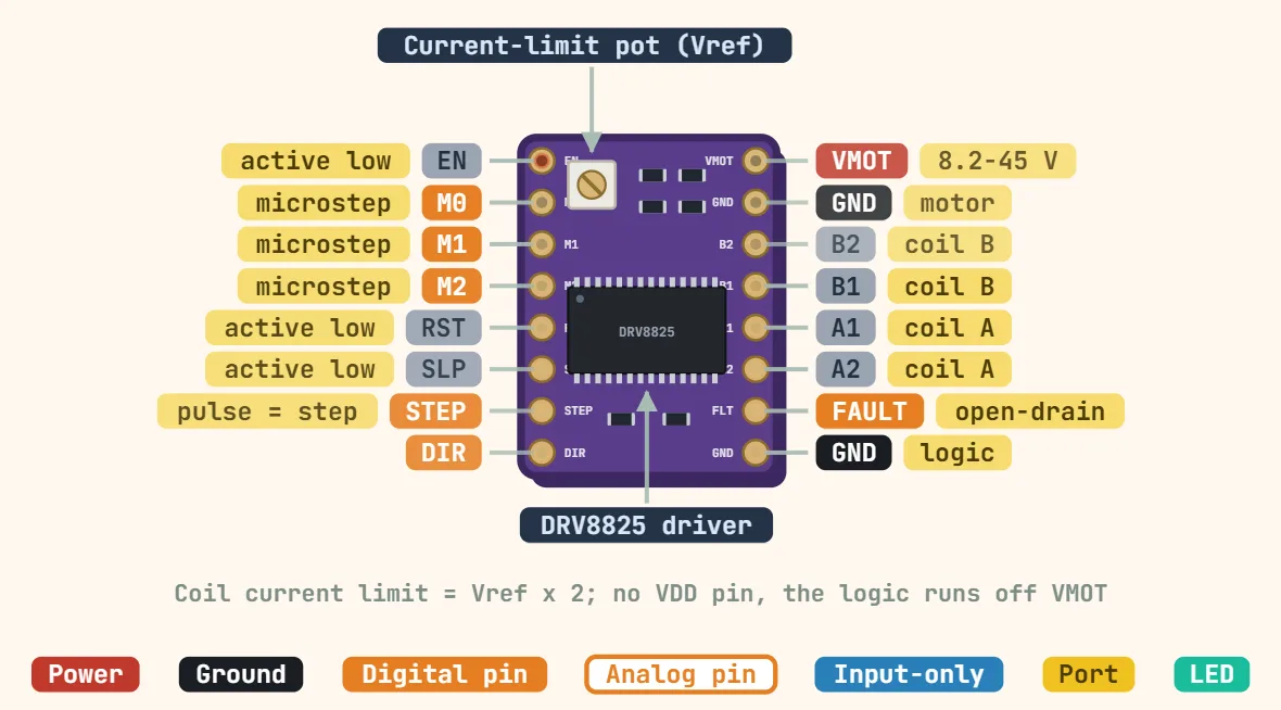
Pinos
- ENABLE (active low — pulled low on the carrier, so the outputs are LIVE when this pin is left unconnected)
- M0 (microstep select bit 0 — pulled low; M2/M1/M0 = 000 full, 001 half, 010 1/4, 011 1/8, 100 1/16, 101 1/32)
- M1 (microstep select bit 1 — pulled low)
- M2 (microstep select bit 2 — pulled low; this trio replaces the A4988's MS1/MS2/MS3 and adds 1/32 stepping, and the truth table is plain binary, not the A4988's)
- RESET (active low — must be HIGH for the driver to step; on the bare carrier it is not driven, which is why a driver that looks correctly wired does nothing. Standard fix: jumper it to SLEEP)
- SLEEP (active low — must also be HIGH to run; jumpering SLEEP to RESET is the usual way to satisfy both at once)
- STEP (one rising edge = one microstep — hold each level at least 1.9µs, so no faster than ~250kHz)
- DIR (direction — its level is sampled on each rising STEP edge)
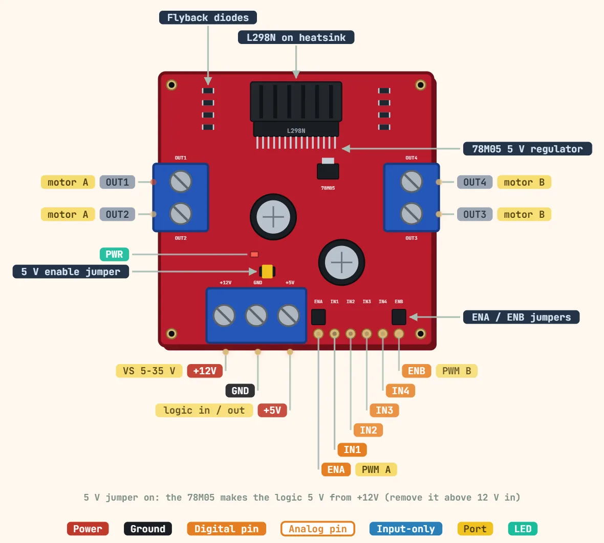
- VMOT (motor supply 8.2–45V, where the A4988 stops at 35V — fit a 100µF electrolytic directly across VMOT/GND, the connection inrush spike is the usual way these die)
- GND (motor-supply ground, the return for VMOT and both coils — 1.5A per coil bare, 2.2A only with a heatsink and airflow)
- B2 (coil B, one end)
- B1 (coil B, other end — B2/B1 occupy exactly the positions the A4988 prints 2B/2A, same pads, different naming)
- A1 (coil A, one end — set the current limit BEFORE plugging a motor in: on the DRV8825 the limit is Vref × 2, measured on the trimpot screw, not the A4988's formula)
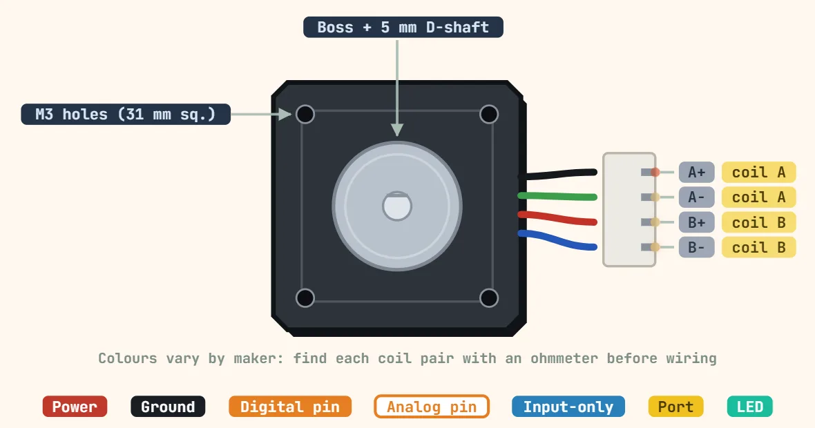
- A2 (coil A, other end — never split one motor winding across an A pin and a B pin; find the two coil pairs with a multimeter before wiring)
- FAULT (open-drain, active low, pulled low on over-current or thermal shutdown — THIS IS THE PIN THAT DIFFERS FROM THE A4988, which has its VDD logic supply in this position. The DRV8825 has no logic-supply pin at all: it runs its logic off VMOT through an internal 3.3V regulator. Check what a socket built for an A4988 drives here before plugging one in)
- GND (logic ground, the return for STEP/DIR/ENABLE and the microstep pins)
Especificações
| Motor supply (VMOT) | 8.2–45 V |
|---|---|
| Logic supply | None needed (internal regulator from VMOT) |
| Nível lógico | 3.3 V and 5 V compatible |
| Output current | ≈1.5 A per phase without heatsink; 2.2 A max with cooling |
| Microstepping | Full, 1/2, 1/4, 1/8, 1/16, 1/32 |
| Current limit | I = 2 × Vref (0.1 Ω sense resistors) |
| STEP pulse | ≥ 1.9 µs HIGH and LOW (≈250 kHz max) |
| Protection | Over-current, over-temperature, under-voltage (FAULT pin) |
| Capacitor | 100 µF across VMOT/GND |
| Tamanho | 15.2 × 20.3 mm |