Pinagem
Pinagem Módulo transceptor CAN bus (MCP2515 + TJA1050)
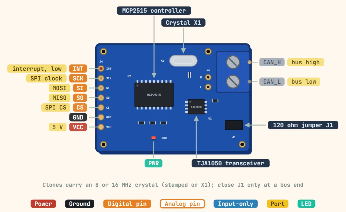
Pinos
- VCC — board supply, 5V on virtually every common breakout (the TJA1050 transceiver on it is a 5V-only part) — don't assume the header is 3.3V-safe just because the MCP2515 die itself tolerates 2.7–5.5V
- GND — ground reference shared by the MCP2515, the TJA1050 and the host MCU
- CS — SPI chip select (SS), active-low; a free MCU digital output, commonly wired to D10 in the widely-used Arduino MCP2515 library examples
- SI — SPI data in (the MCP2515 datasheet's own name for MOSI: master → module)
- SO — SPI data out (the MCP2515 datasheet's own name for MISO: module → master)
- SCK — SPI clock, up to 10MHz per the MCP2515 datasheet
- INT — active-low interrupt request; drops low on a received frame, TX-complete, error or wake event so firmware can react without polling the controller over SPI
- CAN_H / CAN_L — the differential bus pair, broken out on its own screw terminal rather than the SPI header — this is the pair that actually runs to the rest of the CAN network
- Termination jumper (often silkscreened near the screw terminal) — bridges an onboard 120Ω resistor across CAN_H/CAN_L; only close it on a module that sits at a true physical end of the bus
Especificações
| Controlador | Microchip MCP2515 (CAN 2.0B) |
|---|---|
| Transceptor | NXP TJA1050 |
| Tensão de alimentação | 5 V (TJA1050 is 5 V only) |
| Nível lógico | 5 V (level-shift for 3.3 V MCUs) |
| CAN bit rate | Up to 1 Mbps |
| SPI clock | Up to 10 MHz |
| Buffers | 3 TX, 2 RX; 6 filters, 2 masks |
| Cristal | 8 MHz or 16 MHz (check the can) |
| Terminação | 120 Ω via jumper, only at bus ends |
| Bus connection | CAN_H / CAN_L screw terminal |
Notas
- Clone boards circulate with either an 8MHz or 16MHz crystal (stamped on the small silver can next to the MCP2515) — the CAN library's bit-timing setting has to match whichever one is actually fitted, or the node fails to talk on the bus even though SPI communication with the chip itself works fine; check the crystal rather than assuming a value from a tutorial.
- A CAN trunk should only be terminated at its two true physical ends: closing every module's onboard 120Ω jumper because it's there pulls the combined load resistance below what the TJA1050 is specified to drive and degrades the differential signal for every node on the bus — leave the jumper open on any module that sits in the middle.
- The TJA1050 is a 5V-only transceiver with no onboard level shifting on most of these boards, so once VCC is 5V the whole header — SI/SO/SCK/CS/INT included — runs at 5V logic; wiring it straight into a 3.3V-only MCU's GPIOs (ESP32, STM32, RP2040, …) risks damaging them. Add a logic-level shifter, or choose a board built around the TJA1051T/3 — not the plain TJA1051T, which NXP designed as a straight 5V-only, pin-compatible swap for the TJA1050. The /3 variant adds a dedicated VIO pin (in place of the N.C. pin on the TJA1050/TJA1051T) that must be tied to the MCU's own supply rail to get genuine 3.3V-compatible logic levels; a more commonly stocked hobbyist option is a 3.3V transceiver board built around the TI SN65HVD230 instead.
- This module is the SPI-to-CAN add-in board (an MCP2515 controller plus a TJA1050 transceiver) that lets an MCU with no native CAN peripheral join a bus — it is not the bus itself. The plain 'CAN bus (2-wire)' pinout elsewhere in this app documents only the CAN_H/CAN_L/GND trunk wiring; this entry is the controller board wired onto one end of that trunk.