Calculateur en ligne gratuit
Temporisateur NE555
Astable
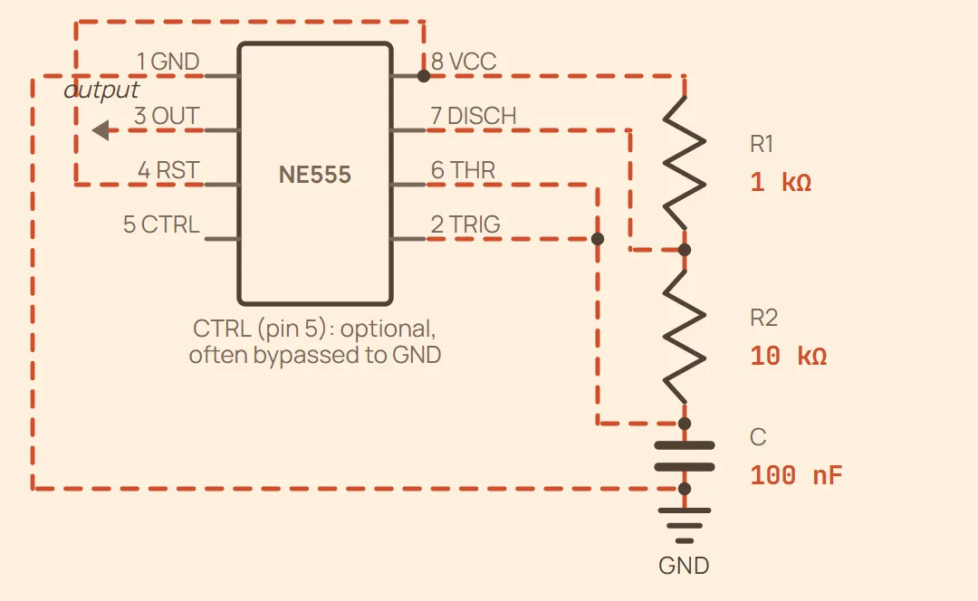
Réseau de temporisation entièrement câblé — les broches sont regroupées par fonction, pas dans l'ordre physique du boîtier DIP (voir la fiche 555 timer dans Pinouts pour la vraie disposition des broches). RST est relié à VCC pour garder la puce active ; OUT est la sortie en signal carré (vers la charge que vous pilotez) ; CTRL est laissé comme indiqué car il est facultatif en fonctionnement de base.
Exemple Fréquence: 685.7 Hz — rapport cyclique : 52.38 %
Rapport cyclique — indiqué ci-dessous en pourcentage. Il ne peut jamais atteindre 50 % : le condensateur se charge à travers R1 + R2 mais se décharge à travers R2 seule, donc la phase haute est toujours la plus longue.
Ce que vous saisissez
- R1 (Ω)
- R2 (Ω)
- C
Monostable
Fully wired timing network — pins are grouped by function, not physical DIP order (see the 555 timer entry in Pinouts for the real pin layout). Pin 2 (TRIG) is not part of the R/C network — it needs a separate external trigger pulse. RST is tied to VCC to keep the chip enabled; OUT is the pulse output; CTRL is left as noted since it's optional for basic operation.
Exemple Pulse width: 110 ms
One-shot pulse width: — the pulse starts when pin 2 (TRIG) is pulled below ⅓ Vcc.
Ce que vous saisissez
- R (Ω)
- C
Bistable
Pins grouped by function, not physical DIP order (see the 555 timer entry in Pinouts for the real pin layout). Pulling SET below ⅓ Vcc latches OUT high; pulling RESET above ⅔ Vcc latches OUT low. DISCH (pin 7) is left unconnected — there's no timing capacitor to discharge in this mode. RST (pin 4) is tied to VCC to keep the chip enabled.
Exemple No timing formula in this mode — OUT just follows whichever input (SET/RESET) was driven most recently. 10 kΩ is a typical pull resistor value; lower it if noise is falsely triggering an input.
No timing capacitor — SET (pin 2) and RESET (pin 6) are level-controlled inputs, each held to its resting state by a pull resistor until driven the other way.
Ce que vous saisissez
- Pull-up R — SET (Ω)
- Pull-down R — RESET (Ω)