Calculadora en línea gratuita
Temporizador NE555
Astable
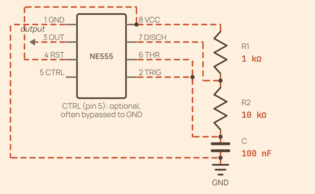
Red de temporización completamente cableada — los pines están agrupados por función, no por el orden físico del DIP (consulta la entrada del temporizador 555 en Pinouts para la disposición real de pines). RST va a VCC para mantener el chip habilitado; OUT es la salida de onda cuadrada (va a la carga que estés controlando); CTRL queda como se indica porque es opcional para el funcionamiento básico.
Ejemplo Frecuencia: 685.7 Hz — ciclo de trabajo: 52.38 %
Ciclo de trabajo — se indica abajo como porcentaje. Nunca puede llegar al 50 %: el condensador se carga a través de R1 + R2 pero se descarga solo a través de R2, así que la fase alta siempre es la más larga.
Lo que introduces
- R1 (Ω)
- R2 (Ω)
- C
Monoestable
Fully wired timing network — pins are grouped by function, not physical DIP order (see the 555 timer entry in Pinouts for the real pin layout). Pin 2 (TRIG) is not part of the R/C network — it needs a separate external trigger pulse. RST is tied to VCC to keep the chip enabled; OUT is the pulse output; CTRL is left as noted since it's optional for basic operation.
Ejemplo Pulse width: 110 ms
One-shot pulse width: — the pulse starts when pin 2 (TRIG) is pulled below ⅓ Vcc.
Lo que introduces
- R (Ω)
- C
Biestable
Pins grouped by function, not physical DIP order (see the 555 timer entry in Pinouts for the real pin layout). Pulling SET below ⅓ Vcc latches OUT high; pulling RESET above ⅔ Vcc latches OUT low. DISCH (pin 7) is left unconnected — there's no timing capacitor to discharge in this mode. RST (pin 4) is tied to VCC to keep the chip enabled.
Ejemplo No timing formula in this mode — OUT just follows whichever input (SET/RESET) was driven most recently. 10 kΩ is a typical pull resistor value; lower it if noise is falsely triggering an input.
No timing capacitor — SET (pin 2) and RESET (pin 6) are level-controlled inputs, each held to its resting state by a pull resistor until driven the other way.
Lo que introduces
- Pull-up R — SET (Ω)
- Pull-down R — RESET (Ω)