Calculadora online gratuita
Impedância controlada
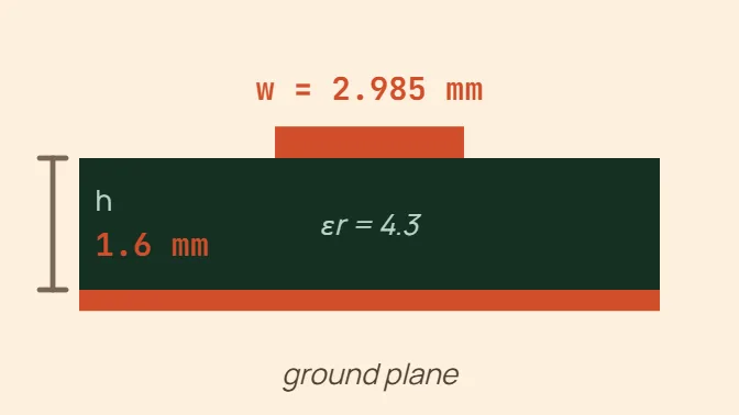
Microstrip
Exemplo w = 2.99 mm (117.5 mil) for 50 Ω on h = 1.6 mm, εr = 4.3, 0.035 mm copper.
A trace over a single reference plane, solved backwards from IPC-2141's own closed-form approximation: . Good to a few percent for 0.1 ≤ w/h ≤ 2 — the zone most single-ended controlled-impedance traces actually fall in.
O que você informa
- Target impedance Z₀ (Ω)
- Dielectric height h
- Dielectric constant εr
- Copper weight
Coplanar (CPW)
Exemplo w = 3.10 mm (122.0 mil) for 50 Ω with a 0.3 mm gap, h = 1.6 mm, εr = 4.3 — assuming no ground plane beneath this layer.
A signal trace with coplanar ground pours either side of it on the SAME layer, over a dielectric with NO continuous ground plane assumed underneath it: , k = w/(w+2·gap). A ground plane close beneath (the common case on a real multilayer stack-up) needs a different, grounded-CPW formula this tool deliberately does not attempt — the published sources for it disagree with each other and could not be reconciled with confidence. Use this mode only when the layer really has no plane directly under it.
O que você informa
- Target impedance Z₀ (Ω)
- Coplanar gap g
- Dielectric height h
- Dielectric constant εr
Differential pair
Exemplo w = 1.05 mm (41.4 mil) each, single-ended Z₀ = 87.07 Ω, for 100 Ω differential with a 0.2 mm gap on h = 1.6 mm, εr = 4.3.
Two matched microstrip traces, close enough to couple: , where s is the EDGE-TO-EDGE gap between them and Z₀ is the single-ended impedance the same two traces would have on their own. Solved backwards from a target Zdiff — pick the gap the layout can actually hold, and this returns the width that reaches it.
O que você informa
- Target differential impedance Zdiff (Ω)
- Edge-to-edge gap s
- Dielectric height h
- Dielectric constant εr
- Copper weight